2-22
X10DAi/X10DAC/X10DAX Motherboard User's Manual
Power Button
OH/Fan Fail LED
1
NIC1 LED
Reset Button
2
HDD LED
Power LED
Reset
PWR
Vcc
Vcc
Vcc
Vcc
Ground
Ground
1920
Vcc
X
Ground
NMI
X
Vcc
PWR Fail LED
NIC2 LED
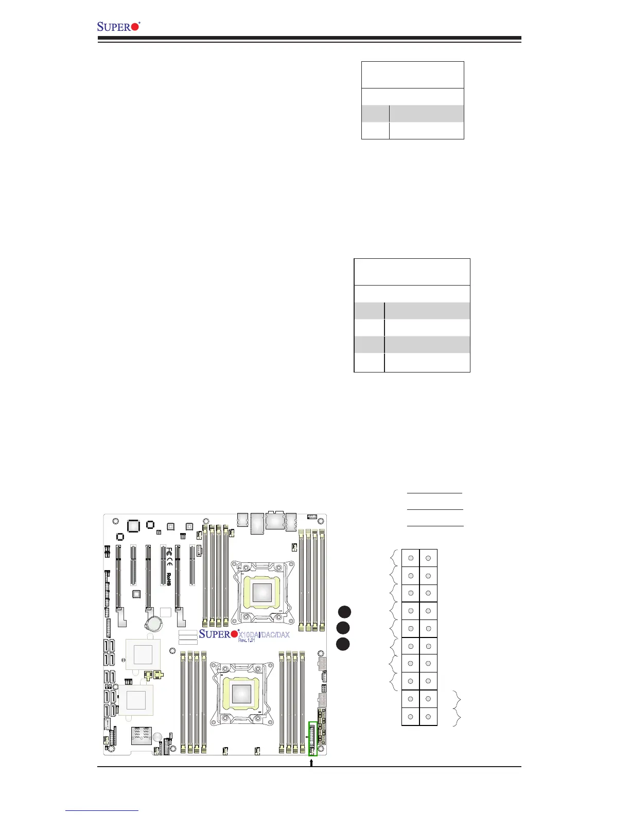
NIC1/NIC2 LED Indicators
The NIC (Network Interface Control-
ler) LED connection for GLAN port 1 is
located on pins 11 and 12 of JF1, and
the LED connection for GLAN Port 2 is
on Pins 9 and 10. Attach the NIC LED
cables here to display network activity.
Refer to the table on the right for pin
denitions.
HDD LED
The HDD LED connection is located
on pins 13 and 14 of JF1. Attach a
cable here to indicate HDD activ-
ity. See the table on the right for pin
denitions.
HDD LED
Pin Denitions (JF1)
Pin# Denition
13 3.3V Standby
14 HD Active
A. HDD LED
B. NIC1 LED
C. NIC2 LED
GLAN1/2 LED
Pin Denitions (JF1)
Pin# Denition
9 NIC 2 Activity LED
10 NIC 2 Link LED
11 NIC 1 Activity LED
12 NIC 1 Link LED
A
B
C
JAUDIO1
JPL1
JPL2
BT1
CLOSE 1st
OPEN 1st
BIOS
BIOS
X10DAi/DAC/DAX
Rev. 1.01
Battery
PCH
LAN CTRL
LAN CTRL
Audio CTRL
SAS
CTRL
FAN7
FP CTRL
LE2
JS7
UARTO
CLOSE 1st
OPEN 1st
SAS CODE
J24
JF1
JSTBY1
FAN2
FAN6
FAN1
FANA
FAN4
FAN3
FAN5
DS1
SP1
J23
JWD1
JI2C1
J30
JPME2
JI2C2
J29
JBR1
J19
JPS1
T-SGPIO3
T-SGPIO1
T-SGPIO2
JTPM1
JSD2
JSD1
JL1
JSPDIF_IN1
JSPDIF_OUT1
JD1
JPP1
JPP0
JS5
JPWR2
JPWR1
JPI2C1
JTBT1
JS2
JS6
BIOS
LICENSE
MAC CODE
BAR CODE
USB0/1
AUDIO_FP
I-SATA5
MDIO
SAS4~7
USB9/10(3.0)