2-24
X10DAi/X10DAC/X10DAX Motherboard User's Manual
Power Button
OH/Fan Fail LED
1
NIC1 LED
Reset Button
2
HDD LED
Power LED
Reset
PWR
Vcc
Vcc
Vcc
Vcc
Ground
Ground
1920
Vcc
X
Ground
NMI
X
Vcc
PWR Fail LED
NIC2 LED
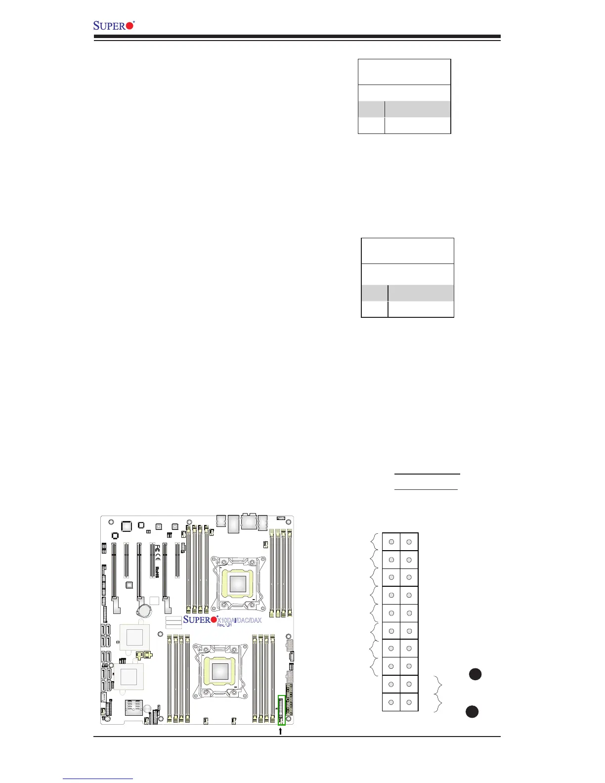
Power Button
The Power Button connection is located
on pins 1 and 2 of JF1. Momentarily
contacting both pins will power on/off the
system. Refer to the table on the right for
pin denitions.
Power Button
Pin Denitions (JF1)
Pin# Denition
1 Signal
2 Ground
Reset Button
The Reset Button connection is located
on pins 3 and 4 of JF1. Attach it to a
hardware reset switch on the computer
case. Refer to the table on the right for
pin denitions.
Reset Button
Pin Denitions (JF1)
Pin# Denition
3 Reset
4 Ground
A. Reset Button
B. PWR Button
A
B
JAUDIO1
JPL1
JPL2
BT1
CLOSE 1st
OPEN 1st
BIOS
BIOS
X10DAi/DAC/DAX
Rev. 1.01
Battery
PCH
LAN CTRL
LAN CTRL
Audio CTRL
SAS
CTRL
FAN7
FP CTRL
LE2
JS7
UARTO
CLOSE 1st
OPEN 1st
SAS CODE
J24
JF1
JSTBY1
FAN2
FAN6
FAN1
FANA
FAN4
FAN3
FAN5
DS1
SP1
J23
JWD1
JI2C1
J30
JPME2
JI2C2
J29
JBR1
J19
JPS1
T-SGPIO3
T-SGPIO1
T-SGPIO2
JTPM1
JSD2
JSD1
JL1
JSPDIF_IN1
JSPDIF_OUT1
JD1
JPP1
JPP0
JS5
JPWR2
JPWR1
JPI2C1
JTBT1
JS2
JS6
BIOS
LICENSE
MAC CODE
BAR CODE
USB0/1
AUDIO_FP
I-SATA5
MDIO
SAS4~7
USB9/10(3.0)