 Loading...
Do you have a question about the Supero X10DAi and is the answer not in the manual?
| Chipset | Intel C612 |
|---|---|
| Memory Type | DDR4 |
| Max Memory | 1TB |
| CPU Socket | LGA 2011-3 |
| CPU | Dual Intel Xeon E5-2600 v3/v4 |
| Memory Slots | 16 DIMM slots |
| Expansion Slots | 3x PCI-E 3.0 x16 slots, 3x PCI-E 3.0 x8 slots |
| SATA Ports | 10x SATA3 (6Gbps) ports |
| LAN | Dual Intel i350 GbE LAN |
| Audio | Realtek ALC888S |
| RAID Support | RAID 0, 1, 5, 10 |
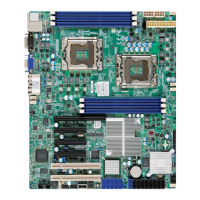
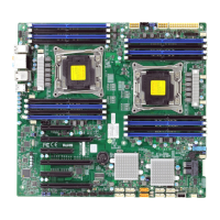
Details the Super X10DAi/X10DAC/X10DAX motherboard's features and compatibility.
Outlines the structure and content of the manual's chapters and appendices.
Explains symbols and conventions used for important warnings and notes in the manual.
Provides contact information for Supermicro's headquarters, Europe, and Asia-Pacific offices.
Introduces the motherboard, lists retail box contents, and provides support links.
Illustrates and labels the various connectors and components on the motherboard.
Details jumper settings and lists various connectors on the motherboard.
Explains the function and status of various LED indicators on the motherboard.
Details key motherboard features including CPU, memory, chipset, and expansion slots.
Describes the motherboard's SATA and SAS port capabilities and RAID support.
Details CPU monitoring, fan control, LED indicators, and system management features.
Provides a visual representation of the motherboard's internal architecture and component connections.
Discusses the Intel E5-2600v3 processors and the C612 chipset's capabilities.
Explains features like Recovery from AC Power Loss and system health monitoring.
Details system health monitoring, fan status, temperature control, and resource alerts.
Describes ACPI for power management and system event handling.
Provides requirements and warnings regarding the power supply for the motherboard.
Presents industry-standard warnings related to potential bodily injury during installation.
Provides guidelines for product disposal according to national laws and regulations.
Explains precautions for handling static-sensitive components to prevent ESD damage.
Details the process of installing the motherboard into a chassis, including tools and mounting holes.
Guides on installing the CPU and heatsink, with warnings about proper handling.
Guides on how to install and remove DIMM memory modules from the slots.
Introduces motherboard connectors and I/O ports, showing their locations.
Explains the various USB ports and headers on the motherboard with pin definitions.
Details the onboard HD audio codec and front panel audio header.
Explains the front control panel connectors and their functions.
Provides pin definitions for NMI Button, Power LED, HDD LED, NIC LEDs.
Details pin definitions for Overheat/Fan Fail LED and Power Fail LED.
Provides pin definitions for the Reset Button and Power Button.
Explains how to connect power cables, including ATX and CPU power connectors.
Describes fan headers and the chassis intrusion header for security monitoring.
Details speaker and power LED connections for system feedback.
Explains TPM/Port 80 header and standby power header for security and wake-up.
Explains the Power SMB connector for monitoring power supply and system temperatures.
Describes SGPIO headers and SATA_DOM power connectors for device connectivity.
Explains SPDIF headers for audio support.
Introduces jumper settings for modifying motherboard operations.
Details jumper settings for enabling or disabling Gigabit LAN ports.
Instructions for clearing CMOS and using the Watch Dog jumper for system monitoring.
Details jumpers for manufacturer mode and SAS enable functionality.
Describes the function and status of onboard LED indicators for LAN and Power.
Explains the SAS heartbeat LED status at DS1.
Details the SATA and SAS connection ports and their pin definitions.
Provides general procedures for troubleshooting system issues.
Covers troubleshooting steps for common issues like no video and system boot failure.
Addresses troubleshooting for loss of system setup configuration (CMOS).
Details how to troubleshoot memory-related errors, including compatibility and installation.
Provides checks for system instability during or after OS installation.
Outlines steps to take before contacting technical support and information to provide.
Provides instructions for removing and installing the onboard battery.
Answers common questions regarding memory support and BIOS updates.
Explains the process for returning products for warranty service, including RMA.
Introduces the AMI BIOS setup utility and basic navigation.
Guides on accessing the BIOS setup utility and describes the initial Main setup screen.
Details items displayed in the Main BIOS setup screen like date, time, and memory.
Introduces the Advanced Setup menu for configuring system parameters.
Options for configuring boot display (POST messages vs. OEM logo).
Covers error handling, boot retries, and power configuration.
Details power management settings including EuP, Watch Dog, and AC power loss behavior.
Displays CPU information and allows configuration of CPU settings.
Covers CPU settings like clock spread, hyper-threading, core enablement, and execute disable bit.
Details CPU features like AES-NI, virtualization, and advanced power management.
Settings for CPU P-states, including EIST, Turbo Mode, and C-states.
Introduces chipset configuration settings.
Allows configuration of settings for the Intel North Bridge.
Configuration options for the Intel Integrated I/O (IIO) controllers.
Settings for Intel I/O Acceleration and VT-d support for I/O virtualization.
Settings for QPI link speed, L0p/L1 enable, and early snoop.
Settings for memory frequency, data scrambling, and power limits.
Configuration for memory RAS settings like RAS Mode and Memory Rank Sparing.
Displays status information for installed DIMM modules.
Configuration settings for PCI, PCIe, and Plug-and-Play devices.
Settings for PCI latency, VGA palette, and error reporting.
Covers settings for 4G decoding, SR-IOV, and PCI-E maximum payload.
Settings for PCI-E read requests and Active State Power Management (ASPM).
Settings for MMIO memory sizes and PCI device option ROM support.
Selects the type of device for onboard LAN option ROM boot.
Enables PXE or UEFI support for network stack.
Configuration for trusted computing features and TPM settings.
Settings for ACPI, including WHEA support, HPET, and NUMA.
Configuration for Intel Thunderbolt features, including hot-plug support.
Thunderbolt settings for PCIe cache size and SMI notifications.
Feature to configure Event Log settings, including SMBIOS events.
Allows configuration of SMBIOS event logging and error reporting.
Settings for memory error thresholds and erasing event logs.
Menu for configuring system security settings, including passwords.
Sets the administrator password required to enter BIOS setup.
Sets the user password required to access BIOS setup utility.
Feature to configure system boot settings and priorities.
Configures boot mode (Legacy, UEFI, Dual) and boot device order.
Options to add or delete boot devices from the priority list.
Options for saving changes, resetting, or discarding settings in BIOS.
Features to restore default settings or save custom configurations.
Lists BIOS beep codes and their corresponding error messages and descriptions.
Guides on installing software programs and drivers after OS installation.
Details on configuring SuperDoctor 5 for hardware monitoring.
Provides an overview of the Unified Extensible Firmware Interface (UEFI) BIOS.
Explains the structure of a UEFI BIOS flash chip and recovery process.
Steps for recovering the main BIOS block using a USB device.
Continues the step-by-step guide for BIOS recovery via USB.