396-3815Y1 SureFire PumpRight for Raven RCM 50 Revised 01/16/2018
1. Pump Won’t Run—Start the Calibrate PWM Limits Test. Press (+) to run the PWM Duty Cycle (DC) to
100%. With a voltmeter check voltage at the 2-pin PWM connector at the EPD or hydraulic valve solenoid.
You should have 12-13 volts. If there is voltage here, but the pump won’t run, check the pump using the fol-
lowing tests:
Electric Pump—Start Calibrate PWM Limits Test to open Section Valves. Unplug the two big connectors
that plug into the black EPD module on the pump tower. Plug these together. This will take power from the
battery directly to the pump(s). The pump(s) should run full speed.
Hydraulic Pump—On the hydraulic valve block, pop up the Manual Override button (red knob on top of sole-
noid). If unit has been in the field, you may need to loosen the dirt to move the knob. In cab, turn hydraulic
flow to very low. Start Calibrate PWM Limits Test to open Section Valves. Engage hydraulics. Pump should
begin turning. Slowly increase hydraulic flow to speed up pump.
2. Pump runs and liquid flows, but display is not reading flow. Unplug the flowmeter. With a voltmeter, check
for 12 volts between pins 1 (black) and 2 (red) of the connector that plugs into the flowmeter. (You may have
to remove the red keeper to get access to the pins with your voltmeter. Be careful not to break the sides of
the red keeper.) You should also have 4-5 volts between pins 1 (black) and 3 (red).
If the voltage is OK, conduct a tap test. Have one person on the display go to Diagnostics > System Infor-
mation > Delivery System, watching Flow Meter (Hz). The second person will tap repeatedly between pins 1
and 3 on the flowmeter connector with a bent paper clip or short piece of wire. As the person taps, the dis-
play should show some numbers on Flow Meter (Hz).
If the voltages are good, and the tap test shows on the display, but the system does not read flow when liquid
is flowing, the flowmeter is not working.
3. PWM Startup—For best startup performance, set the PWM Startup at or slightly above the DC% that the
system will be running at in the field.
TROUBLESHOOTING TIPS:
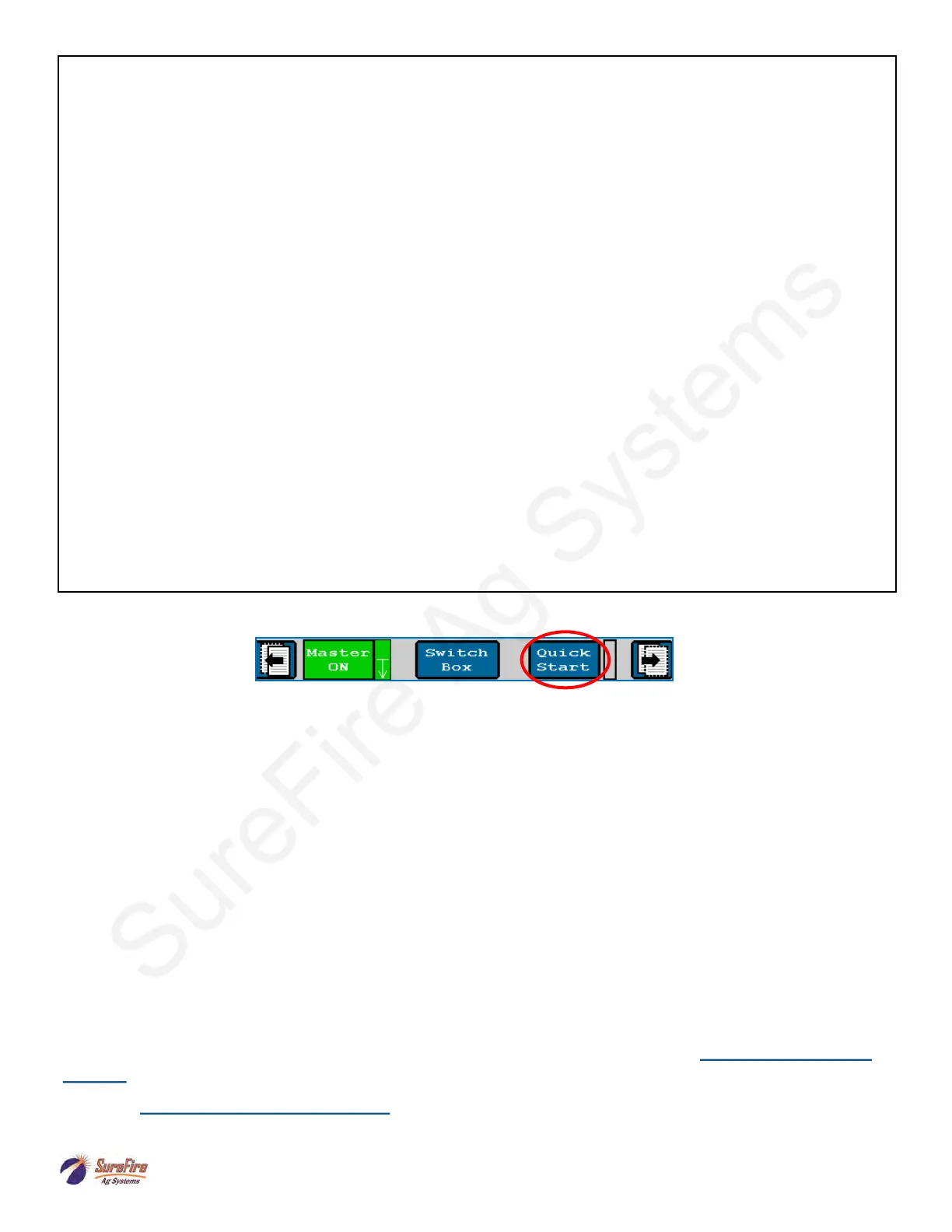
Using the Quick Start button:
Use the Quick Start button to get the system primed and ready to apply when entering a field or starting in a
field corner. Turn on the Master Switch, push Quick Start, the system will begin applying as if the Speed is 3
mph. Start driving. The Auto Rate Control will take over when the speed reaches the Minimum Application
speed. Quick Start runs for 15 seconds. For additional time, push Quick Start again.
Virtual Terminal (VT), Universal Terminal (UT), and Task Controller (TC)
VT or UT software allows the display to show the ISOBUS Implement (the Raven RCM) on the display
screen. This usually comes with the display, but be sure the software is installed if the display has not
previously been used as a Virtual Terminal.
Task Controller software is necessary to do Section Control, Variable Rate Application using prescriptions,
and/or As-Applied Mapping. Task Controller is typically purchased from the display manufacturer as an
Unlock.
See the Task Controller documentation from your display manufacturer for more information on setup and
operation.
For more information, see the SureFire Manual for your Raven RCM system at www.surefireag.com/
support.
Read the Raven RCM Operator’s Manual for safety information and additional setup/operating
information.