396-3815Y1 SureFire PumpRight for Raven RCM 53 Revised 01/16/2018
1. Be sure Pressure Sensor is plugged into Pressure Sensor 1 connector. Make sure
the pins where the harness screws on to the end of the sensor have not been bent.
2. Be sure Pressure Sensor is set up and calibrated in the display.
Setup > System Settings > Pressure Sensor Setup > Check the box for Pressure Sensor 1 > Calibrate
Pressure Sensor > Voltage-based Calibration > 50 mv/PSI.
3. There should be a green LED light on the end of the pressure sensor. This may be difficult to see in daylight. The
sensor needs 12 v. Check between pins B&C on the Pressure 1 connector on harness that connects to the pressure
sensor. If there is no voltage here, check the voltage between pins 1 & 2 on the 12-pin connector labeled PUMP.
4. Go to Diagnostics > System Information > Pressure Sensors for complete information on what the pressure
sensor is doing. O Pressure Voltage should be 0.00 v (or maybe 0.01 v).
No Flow shown on display but liquid is being pumped
Flowmeter Tap Test
1. Unplug the flowmeter. With a voltmeter, check for 12 volts between pins 1 (black) and 2 (red) of
the connector that plugs into the flowmeter. (You may have to remove the red keeper to get
access to the pins with your voltmeter. Be careful not to break the sides of the red keeper.) You
should also have 4-5 volts between pins 1 (black) and 3 (blue).
2. If the voltage is OK, conduct a tap test. Have one person on the display go to Diagnostics > System Information >
Delivery System, watching Flow Meter (Hz). The second person will tap repeatedly between pins 1 and 3 on the
flowmeter connector with a bent paper clip or short piece of wire. As the person taps, the display should show some
numbers on Flow Meter (Hz).
3. If the voltages are good, and the tap test shows on the display, but the system does not read flow when liquid is
flowing, the flowmeter is not working.
4. SureFire has a Speed/Flow Simulator (PN 219-01462) that can be used to confirm if the wiring is good between the
flowmeter and controller.
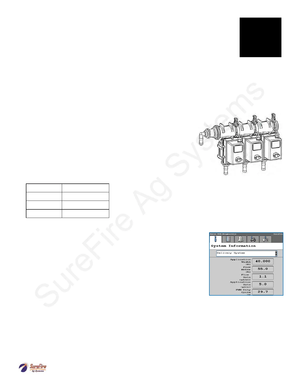
1. Go to Diagnostics > Tests > Control/Section Test to investigate this issue.
2. In Section Test, check and uncheck the boxes. With the box checked the
valve should turn on. The valve should be off with the box not checked.
3. Check the harness connection to that valve. It is a 3-Pin Weather Pack con-
nector. See Section D for wiring diagrams
4. Check voltage pin A to Pin B. Must be 12 volts, if not, go back to 14-pin and
check voltage (pins 1 & 2 are +12V, pins 3 & 4 are ground).
5. If voltage is present on pins A&B of 3 pin connection to valve, then check
Pin C to Pin B. This should be 12 volts when the valve is commanded on or
open, this should be zero volts when valve is off or closed.
6. If signal voltage is not present to open valve, use diagrams to check at the
14-pin , then the ECU for voltage on the proper pin for that section.
7. If constant voltage (Pins A&B) and switched voltage (Pins C&B) are pre-
sent, inspect, repair or replace the valve.
8. Move connector to a different valve and move a different connector to this valve to see if the problem is the valve or
the harness.
Section Valve(s) will not move
Pin Function
A + 12 V Constant
B Ground
C
+ 12 V Signal
Troubleshooting Tip
1. Useful information is available at Diagnostics—System Information—Delivery
System.
2. Check flowmeter operation here.
3. See PWM Duty Cycle (an indication of how fast the pump is running (0-100%). You
can also place PWM DC% on the Run Screen.
Pressure Sensor is not reading
G
Trouble-
shooting