No load tunning,F0-01=0
Set as operation panel control
F1-11=2
Phenomenon: The indicator “tune” lights on the top of operation panel, making the output to the side circuit
through. Press key RUN, the operation panel’s indicator RU N lights, and then tuning begins
F1-00=1
Select as synchronous motor
Set parameters according to the motor’s nameplate: F1-
01, F1-02, F1-03, F1-04, F1-05
And encoder’s pulse number: F1-12
After the tuning, set F0-02=10.00Hz. Press key
RUN, and check if the motor is running normally. If
not, please change the
pulse wheel encoder’s
signal direction and start re-tuning.
F0-01=0(No load tunning)
Or (with load tuning )
Lift the car cage to make the motor off
the load
Recover the setting parameter of terminal running
command way state: F0-01=1
Recover the iron rope’s position
In dynamic tuning, the motor is forward and reversal
running. Parameters of F1-06
pulse wheel encoder
magnet pole’s angle are gained through tuning.
Commend to recognize more than three times and it’s
correct if the error of F1-06 is between ±5°.
F1-11=1
F1-11=2
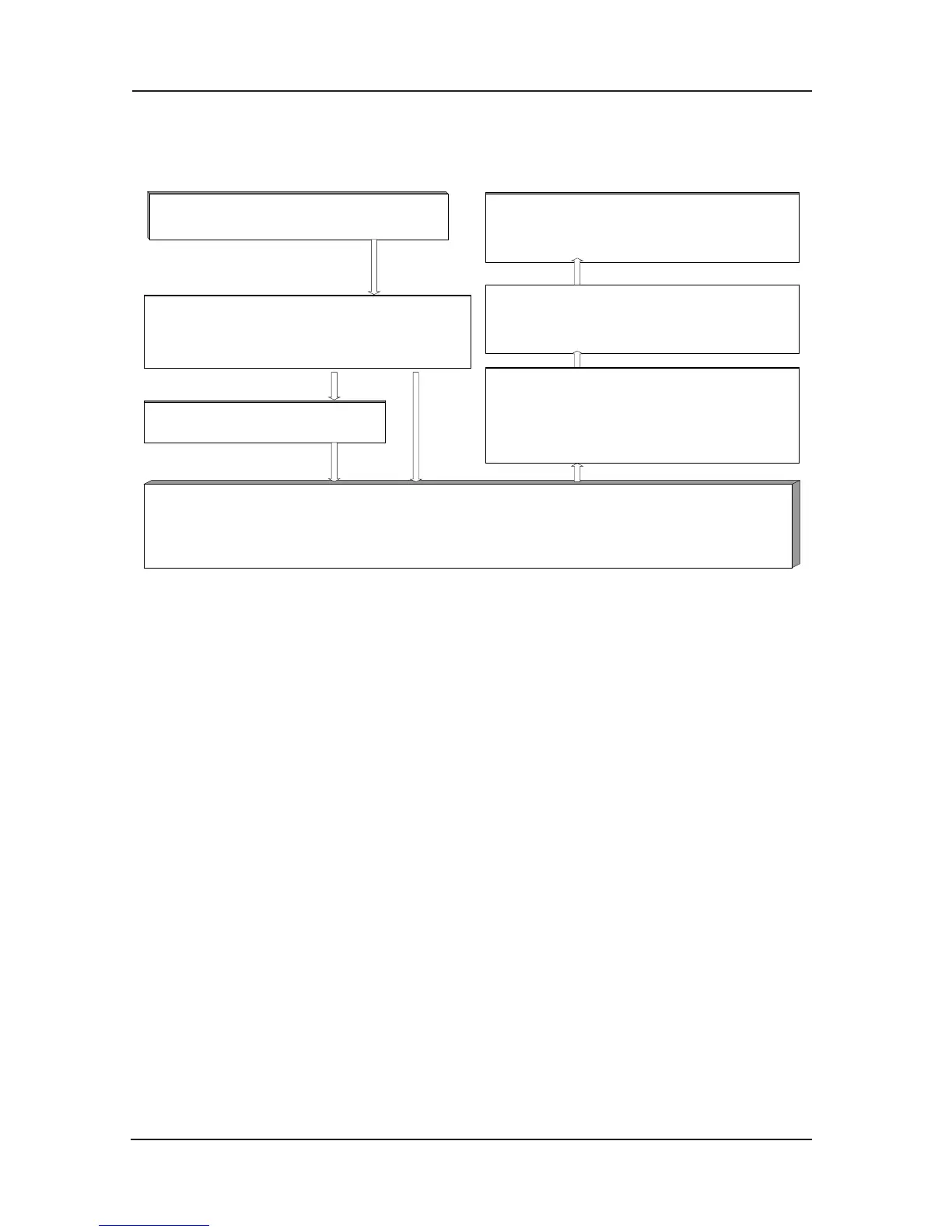
Fig 6-2 Adjusting ow chart of permanent-magnet synchronous motor
Before the first running, the magnet pole identification is necessary for the permanent-magnet
synchronous hoist motor, otherwise it can’t be normally used. After the change of motor
wiring, encoder and encoder wiring, it’s needed to re-recognize the pulse wheel encoder’s
position angle. Therefore, the motor wiring, PG card wiring must
be the same when in
recognizing the magnet pole’s position and the motor normally running. In the identification
course, the motor will run, so you must assure that the synchronous hoist motor which is
recognized must be in no load state.
Before the identification, the parameters of F1 group motor’s nameplate must be inputted
correctly, including rated frequency, rated voltage, rated power, rated r
otation speed, rated
current. And set the encoder’s pulse number (F1-12) correctly. Then set F1-11 as 2 and press
key “confirm”, the inverter will display “TUNE”. Press key RUN, the inverter begins to
recognize. The inverter will display “TUNE” all through the identification course. When the
“TUNE” disappears, the identification is then over.
The result of the identification is the encoder’s installat
ion angle. It’s located in the F1-06
function, and can be checked and modified. The parameter modification is forbidden after the
position identification. Otherwise the inverter can’t run normally.
After the identification, F1-06, F1-08 are setting as motor control reference. Users needn’t
modify it. Otherwise the lift can’t run normally.
If alarming error E20 occurs in the encoder position’s identifica
tion course, please check
whether the PG card is correctly connected. The inverter adopts the vector control mode with
a transducer (assure parameter F0-00 is 1), and it must connect with PG card and encoder
correctly. Otherwise alarm E20 displaying on the panel to indicate encoder’s error.
 Loading...