Terminal Function
J4
Interface of down call button, 2、3 are the input switch value wiring pin,1、4 are
the power wiring pin,used to control button light
J5
Mod-bus communication and power wire terminal,4PIN interface,2、3 are Mod-
bus communication wire pin,1、4 are power wiring pin.
J1~J4 are button interface,details as the following:
Direction for use of MCTC-HCB-F
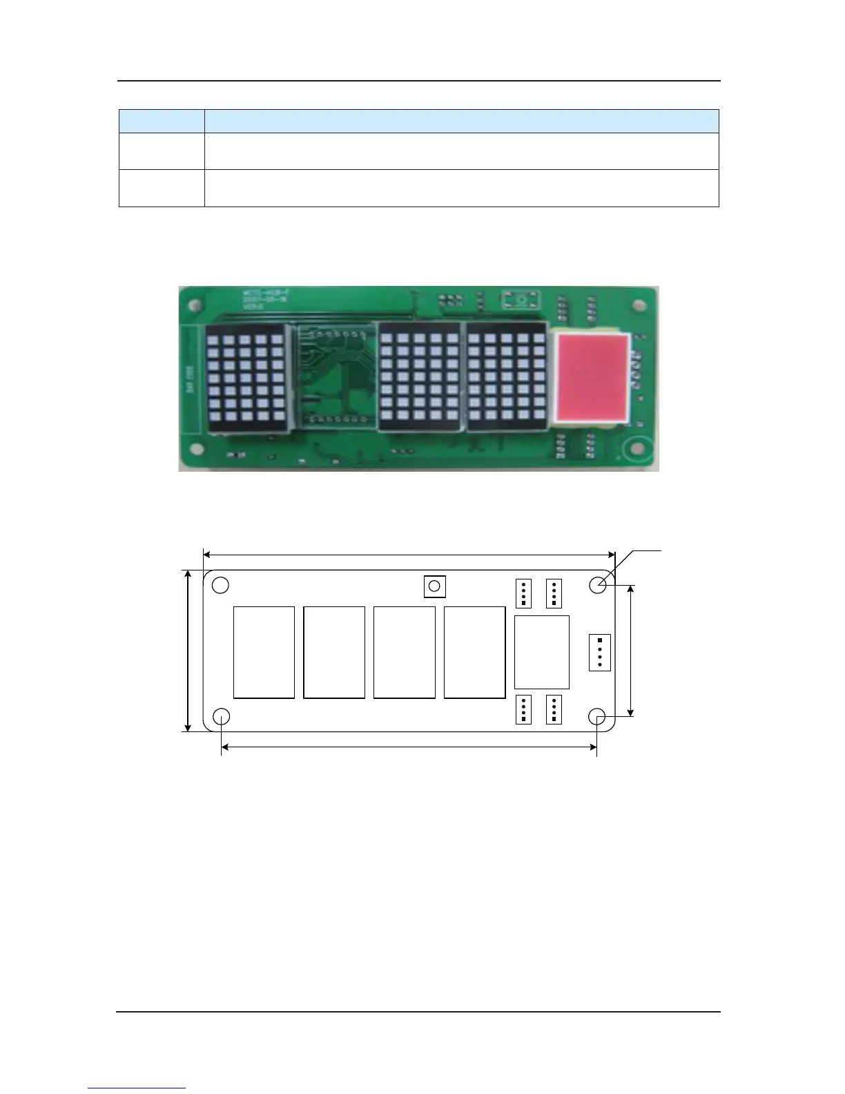
Product Photo of MCTC-HCB-F
Appearance and size (Shown as Fig 3-13)1)
Fig 3-13 Installation size of MCTC-HCB-F
Direction for installation and using2)
Floor address setting and installation modea)
Floor address setting: Press button S1 it will show the setting oor, and release the button for
4s it will return to show the current oor of the car cage. If you keep pressing the button for
more than 4s, it will get into the state of resetting the oor. Each time you pres
s the button, it
will add 1 to the number of the oor. If you keep pressing the button S1, the information of the
oor will add 1 continuously and the maximum setting value is 40. If there’s no pressing in the
continuous 4s, it will store the information of the oor where the displaying panel is in, and twice
shinning of the oor information indicates the successful storage. After 4s it will retur
n to display
the current oor where the car cage is in.
 Loading...