If the oor information setting is 0, it is car display panel;
The oor address is valid oor number (based on the leveling plate), increasing from the bottom
to the top and not related to the actual oor number.
For example: One building has two oors underground, and 10 oors above. Among theses,
Floor 3 and Floor 4 are service oors. So the setting of the dial switch’s oor address is as
follows:
The second floor underground is setting as 1, the first floor underground is setting
as 2, and first oor above the ground is setting as 3, and the second oor above the ground
is setting as 4. If there’s leveling plate between the third oor and the fourth oor, they are
setting separately as 5 and 6, meanwhile, the oors above the fifth oor are setting as 7, 8, 9…;
if there’s no leveling oor be
tween the third oor and the fourth oor, jump through it, and the
oors above the fifth oor are setting as 5, 6, 7….
Plug connection port of locked lift switch and fire switch separately into JP1 and JP2, and plug
connection port of button of up running and down running separately into JP3 and JP4.
Plug connection port used for Mod-bus communication into CN1.
Cautions:
Do not set hall call oor addres
s as 0;
In order to protect communication signals from external disturbance, we advise to use
STP for communication connection;
It is better to use Shielded cable for signal line of communication;
Connect strictly according to terminal signal, and screw down
Definition of input and outputb)
Terminal Name Function Definition
JP1 Switch Interface of locked lift, pin 2 、3 are switch connection pins, pin 4 is lift
lock indicator output
JP2 Switch Interface of fire fighting , pin 2 、3 are switch connection pins, pin 4 is
lift lock indicator output
JP3 Calling button interface of up running , pin 2 、3 are switch connection pins,
pin 1 、4 are power supply pins, for controlling button light
JP4 Call
ing button interface of down running , pin 2 、3 are switch connection pins,
pin 1 、4 are power connection pins, for controlling button light
CN1 Use for communicating with Modbus , pin 2、3 of 4Pin interface are for
communication, pin 1、4 are for power connection
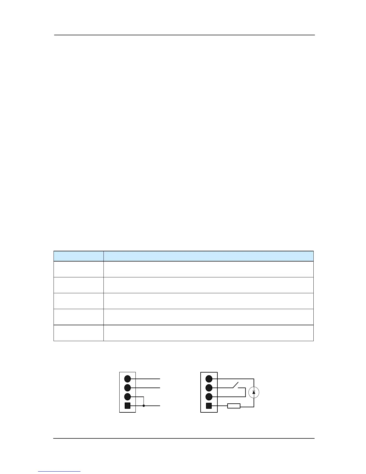
The specific definition of 4 PIN is shown in Fig 3-14. The means of marks in the chart: MP24
(24V Power), KEY-IN (Button input signal), KEY-L
ED (Button light output), GND (0V).
 Loading...