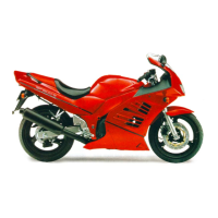
Do you have a question about the Suzuki 125 and is the answer not in the manual?
Engine specifications including type, cylinders, bore, stroke, displacement, compression ratio, fuel system, air cleaner, starter, lubrication, and idle speed.
Specifications for clutch, transmission, gear ratios, final reduction ratio, and drive chain.
Electrical specifications for ignition type, timing, spark plug, battery, generator, fuse, and all lighting.
Chart detailing recommended intervals for periodic service work based on mileage and time.
Procedure for inspecting and adjusting throttle cable play, including specifications and warnings.
Precautions for handling electrical parts, connectors, fuses, switches, and sensors safely.
Factors determining fuel injection time, including basic time, compensations, and sensor signals.
How various sensor signals compensate for fuel injection time (volume) based on engine conditions.
Describes the self-diagnosis function's user mode, notified by the FI indicator light.
Steps to inspect HO2 sensor circuit for output voltage and heater operation.
Service data and specifications for valve and valve guide dimensions and clearances.
Service data and specifications for camshaft and cylinder head dimensions and clearances.
Service data and specifications for cylinder, piston, and piston ring dimensions and clearances.
Service data and specifications for conrod and crankshaft dimensions and clearances.
Service data and specifications for drive train components, gear ratios, and drive chain.
| Fuel System | Carburetor |
|---|---|
| Transmission | 5-speed constant mesh |
| Front Suspension | Telescopic, coil spring, oil damped |
| Ground Clearance | 160 mm |
| Displacement | 124 cm³ |
| Rear Suspension | Swingarm, coil spring, oil damped |
| Front Brake | Disc brake |
| Rear Brake | Drum |
