64 RV125K7 (’07-MODEL)
Step 2
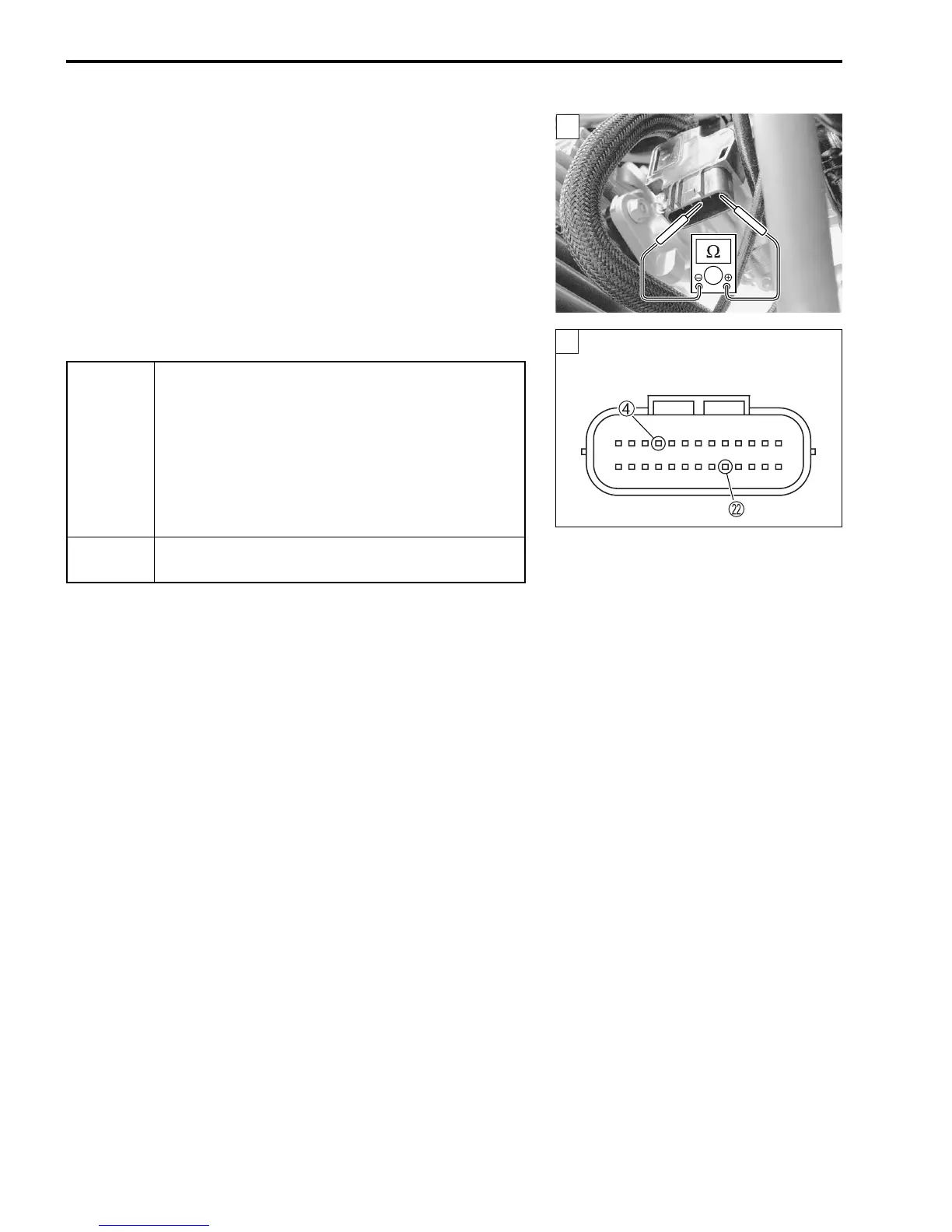
1) Turn the ignition switch OFF.
2) Measure the IAT sensor resistance.
IAT sensor resistance: Approx. 2.56 k
Ω
at 20 °C
Approx. 1.20 k
Ω
at 40 °C
(Terminal – Terminal)
09900-25008: Multi-circuit tester set
Tester knob indication: Resistance (Ω)
Is the resistance OK?
2
YES
• Dg or B/Br wire open or shorted to ground, or
poor L or 4 connection.
• If wire and connection are OK, intermittent trou-
ble or faulty ECM.
• Recheck each terminal and wire harness for
open circuit and poor connection.
• Replace the ECM with a known good one, and
inspect it again.
NO
Replace the throttle body assembly with a new
one.
2
ECM coupler (Harness side)