62 RV125K7 (’07-MODEL)
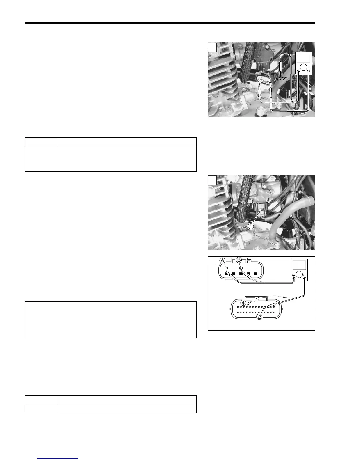
4) Measure the voltage between Dg wire terminal and ground.
5) Also, measure the voltage between Dg wire terminal and B/Br
wire terminal.
IAT sensor input voltage: 4.5 – 5.5 V
(+ R – - Ground)
(+ R – - B/Br)
09900-25008: Multi-circuit tester set
09900-25009: Needle pointed probe set
Tester knob indication: Voltage ()
Is the voltage OK?
Step 1 (When indicating P0110-H:)
1) Turn the ignition switch OFF.
2) Check the IAT sensor coupler for loose or poor contacts.
If OK, then check the IAT sensor lead wire continuity.
3) Disconnect the IAT sensor coupler and ECM coupler.
4) Check the continuity between Dg wire A and terminal L.
5) Also, check the continuity between B/Br wire B and terminal
4.
IAT sensor lead wire continuity:
Continuity ()
09900-25008: Multi-circuit tester set
09900-25009: Needle pointed probe set
Tester knob indication: Continuity test ()
Is the continuity OK?
6) After repairing the trouble, clear the DTC using SDS tool.
(Page 40)
YES Go to Step 2.
NO
• Loose or poor contacts on the ECM coupler
(Terminal L or 4).
• Open or short circuit in the Dg wire or B/Br wire.
1
V
1
When using the multi-circuit tester, do not strongly
touch the terminal of the ECM coupler with a needle
pointed tester probe to prevent the terminal damage
or terminal bend.
1
?
ECM coupler (Harness side)
YES Go to Step 2.
NO Dg wire or B/Br wire open