72 RV125K7 (’07-MODEL)
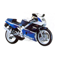
5) If OK, then check the continuity between each terminal and
ground.
ISC valve continuity: ∞ Ω (Infinity)
(Terminal – Ground)
09900-25008: Multi-circuit tester set
Tester knob indication: Resistance (Ω)
Are the resistance and continuity OK?
6) After repairing the trouble, clear the DTC using SDS tool.
(Page 40)
Step 2
1) Turn the ignition switch ON.
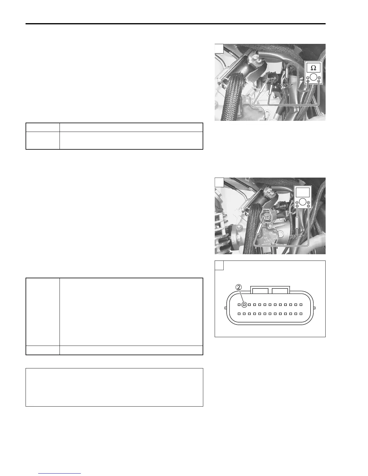
2) Measure the ISC valve voltage between B/O wire and ground.
ISC valve voltage: Battery voltage
(+ B/O – - Ground)
09900-25008: Multi-circuit tester set
Tester knob indication: Voltage ()
Is the voltage OK?
3) After repairing the trouble, clear the DTC using SDS tool.
(Page 40)
YES Go to Step 2.
NO
Replace the ISC valve with a new one.
(Page 88)
1
2
V
YES
• B/O or Y/R wire open or shorted to ground, or
poor 2 connection
• If wire and connection is OK, intermittent trou-
ble or faulty ECM.
• Recheck each terminal and wire harness for
open circuit and poor connection.
• Replace the ECM with a known good one, and
inspect it again.
NO Open circuit in the B/O wire
When using the multi-circuit tester, do not strongly
touch the terminal of the ECM coupler with a needle
pointed tester probe to prevent the terminal damage
or terminal bend.
2
ECM coupler (Harness side)
 Loading...