78 RV125K7 (’07-MODEL)
Step 2 (When indicating 44/P0135:)
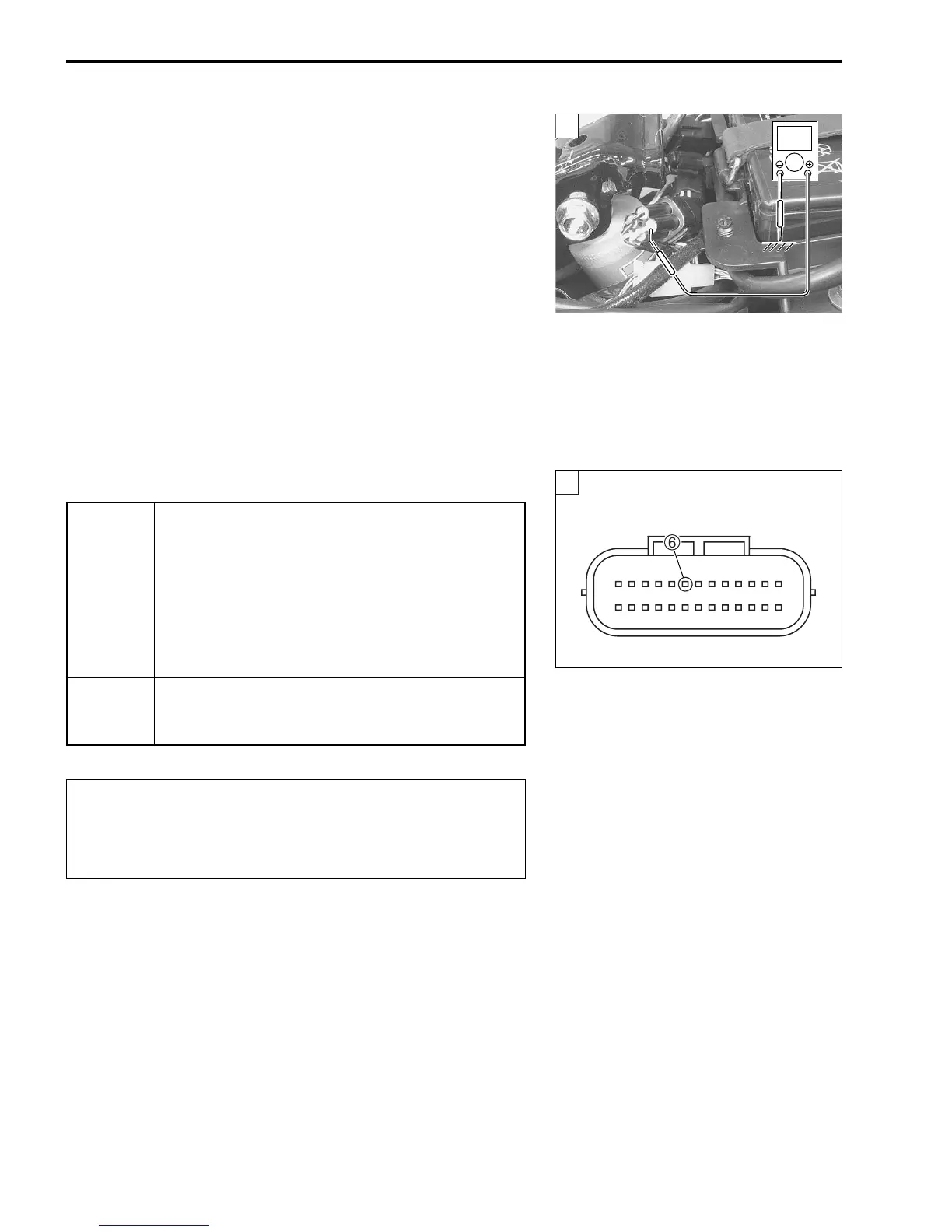
1) Connect the HO2 sensor coupler.
2) Insert the needle pointed probes to the HO2 sensor coupler.
3) Turn the ignition switch ON and measure the heater voltage
between W wire (harness side) and ground.
4) If the tester voltage indicates the battery voltage, it is good
condition.
Heater voltage: Battery voltage
(+ W – - Ground)
NOTE:
Battery voltage can be detected only before starting the engine.
09900-25008: Multi-circuit tester set
09900-25009: Needle pointed probe set
Tester knob indication: Voltage ()
Is the voltage OK?
5) After repairing the trouble, clear the DTC using SDS tool.
(Page 40)
YES
• B/O or W wire open or shorted to ground, or
poor 6 connection.
• Recheck each terminal and wire harness for
open circuit and poor connection.
• If wire and connection are OK, intermittent trou-
ble or faulty ECM.
• Replace the ECM with a known good one, and
inspect it again.
NO
• Open or short circuit in the W wire or B/O wire.
• Loose or poor contacts on the ECM coupler
(terminal 6) or HO2 sensor coupler.
When using the multi-circuit tester, do not strongly
touch the terminal of the ECM coupler with a needle
pointed tester probe to prevent the terminal damage
or terminal bend.
2
V
2
ECM coupler (Harness side)













 To Next Page