ENGINE 3-20
ENGINE COMPONENTS INSPECTION AND SERVICING
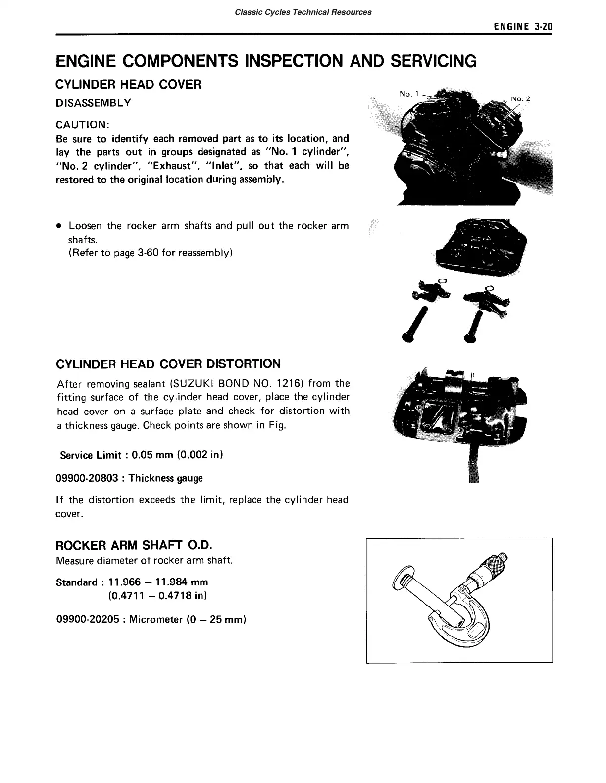
CYLINDER HEAD COVER
DISASSEMBLY
CAUTION:
Be sure to identify each removed part as to its location, and
lay the parts out in groups designated as “No. 1 cylinder”,
“No. 2 cylinder”, “Exhaust”, “Inlet”, so that each will be
restored to the original location during assembly.
l
Loosen the rocker arm shafts and pull out the rocker arm
shafts.
(Refer to page 3-60 for reassembly)
CYLINDER HEAD COVER DISTORTION
After removing sealant (SUZUKI BOND NO. 1216) from the
fitting surface of the cylinder head cover, place the cylinder
head cover on a surface plate and check for distortion with
a thickness gauge. Check points are shown in Fig.
Service Limit : 0.05 mm (0.002 in)
09900-20803
:
Thickness gauge
If the distortion exceeds the limit, replace the cylinder head
cover.
ROCKER ARM SHAFT O.D.
Measure diameter of rocker arm shaft.
Standard
:
11.966 - 11.984 mm
(0.4711 - 0.4718 in)
09900-20205
:
Micrometer (0 - 25 mm)
L
No. 2
Classic Cycles Technical Resources
 Loading...