3-57
ENGINE
l
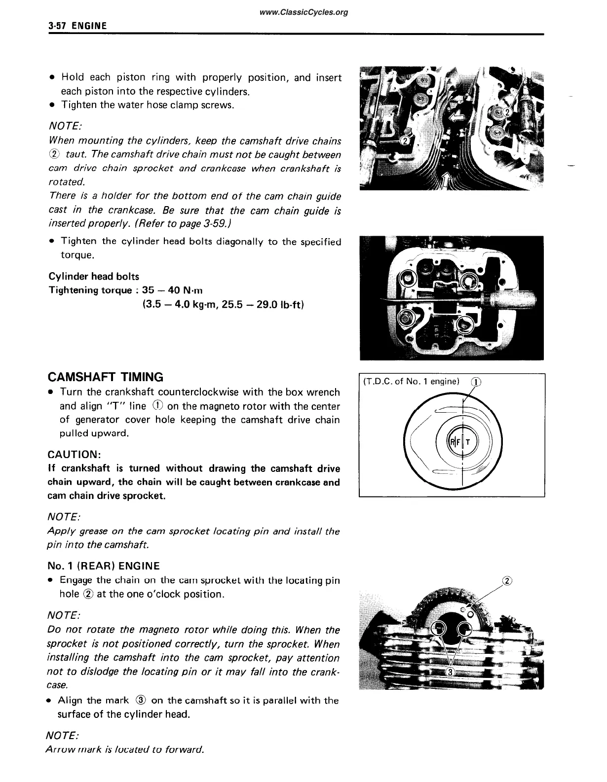
Hold each piston ring with properly position, and insert
each piston into the respective cylinders.
l
Tighten the water hose clamp screws.
NOTE:
When mounting the cylinders, keep the camshaft drive chains
@ taut. The camshaft drive chain must not be caught between
cam drive chain sprocket and crankcase when crankshaft is
rota ted.
There is a holder for the bottom end of the cam chain guide
cast in the crankcase. Be sure that the cam chain guide is
inserted properly. (Refer to page 3-59.)
l
Tighten the cylinder head bolts diagonally to the specified
torque.
Cylinder head bolts
Tightening torque
:
35 - 40 N-m
(3.5 - 4.0 kg-m, 25.5 - 29.0 lb-ft)
CAMSHAFT TIMING
l
Turn the crankshaft counterclockwise with the box wrench
and align “T” line 0 on the magneto rotor with the center
of generator cover hole keeping the camshaft drive chain
pulled upward.
CAUTION:
If crankshaft is turned without drawing the camshaft drive
chain upward, the chain will be caught between crankcase and
cam chain drive sprocket.
NOTE:
Apply grease on the cam
pin in to the camshaft.
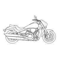
No.
1
(REAR) ENGINE
sprocket locating pin and install the
l
Engage the chain on the cam sprocket with the locating pin
hole @ at the one o’clock position.
NOTE:
Do not rotate the magneto rotor while doing this. When the
sprocket is not positioned correctly, turn the sprocket. When
installing the camshaft into the cam sprocket, pay attention
not to dislodge the locating pin or it may fall into the crank-
case.
l
Align the mark @ on the camshaft so it is parallel with the
surface of the cylinder head.
-
of No. 1 engine) @
I
NOTE:
Arrow mark is located to forward.