44 A-96.250.341 / 061015
AMI Powercon
Maintenance
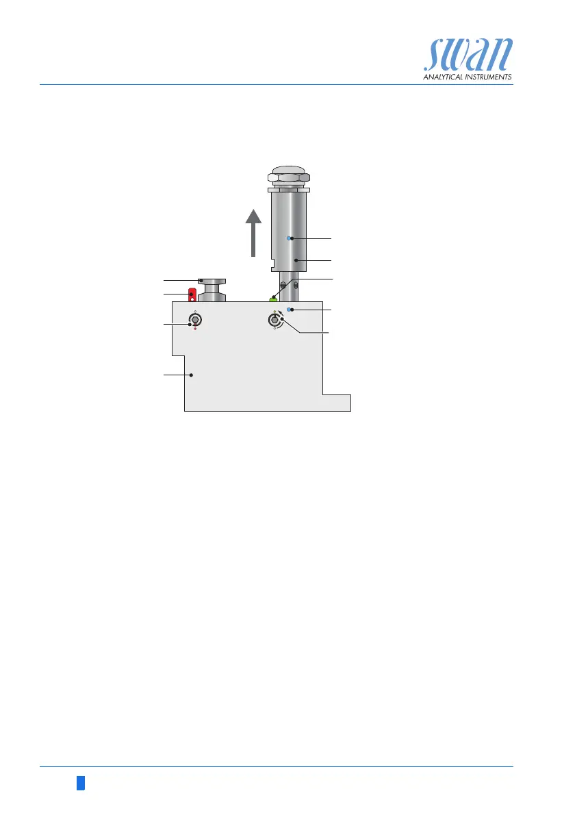
6.3. Maintenance of the Sensor
6.3.1 Remove the Sensor form the Flow Cell
To remove the sensor form the flow cell proceed as follows:
1 Press the locking pin [G] down.
2 Turn the locking screw [H] with a 5 mm allen key counterclock-
wise 180°.
The locking pin remains down.
3 Remove the sensor.
Cleaning If the sensor is slightly contaminated, clean it with soapy water and
a pipe cleaner. If the sensor is strongly contaminated, dip the tip of
the sensor into 5% hydrochloric acid for a short time.
6.3.2 Install the Sensor into the Flow Cell
1 Make sure that the locking mechanism is in unlocked position
(locking pin in position [G] and security screw in position [H]).
2 Put the sensor into the flow cell with the alignment marks [E] in
line.
3 Turn the locking screw with a 5 mm allen key clockwise 180°.
The locking pin moves up in lock position.
A
B
C
D
E
F
G
H
Blind plug
Locking pin locked
Locking screw closed
Flow cell
Alignment marks
Conductivity sensor
Locking pin unlocked
Locking screw open
 Loading...