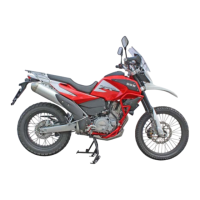
- Sensore pressione e temperatura aria (8) sul cor-
po farfallato.
- Sensore TPS (9) sul corpo farfallato;
- Stepper motor (10) sul corpo farfallato.
L’impianto elettrico è composto dai seguenti ele-
menti:
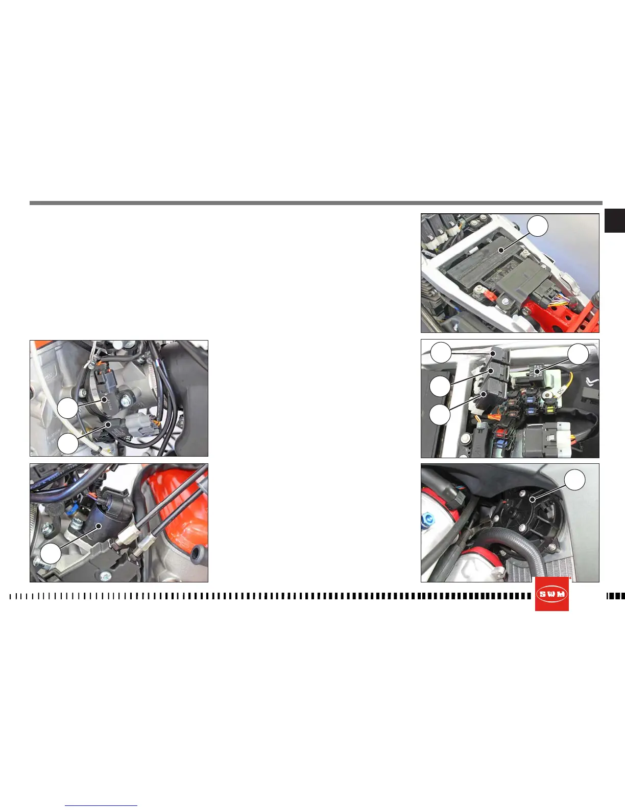
- Batteria 12V-14Ah (11) sotto la sella;
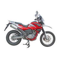
- Dispositivo intermittenza lampeggiatori (12) posto
sulla piastra portautenze sotto la sella;
- Rele posti sulla piastra portautenze sotto la sella;
- Relè (13) elettroventola;
- Relè (13A) iniettore, sonda lambda, pompa ben-
zina, bobina;
- Relè (13B) indicatori di direzione, luci stop, luci
anabbaglianti, luci abbaglianti;
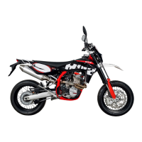
- Elettroventola (14);