18 - 36
4. Operation - Quick Guide
4.1 Measurement Principle
The gauging system uses solid state light sensors (CCD arrays) to analyze an image of the part being
measured. The part is illuminated by parallel (collimated) green light and is moved through a
measurement position on a carriage which is driven by a servo motor, rack and pinion. Movements of
the carriage are monitored by an optical encoder..
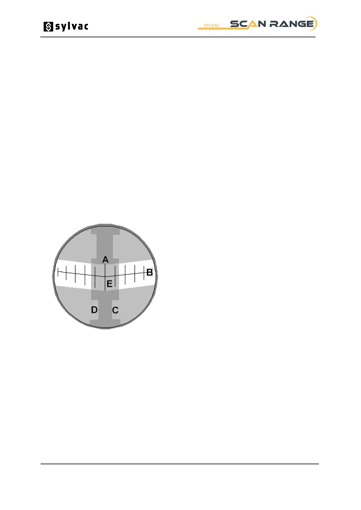
A projector screen is integrated where an optical image of the region surrounding the measurement
position appears at approximately x5 magnification for SYLVAC-Scan 25 (x4 for SYLVAC-Scan 50
and 50 Plus). Reference lines on the screen indicate the nominal measurement center line and also
the location of the measurement position. This latter is in the form of a shallow 'V' corresponding to the
alignment of the CCD arrays in the measurement system.
The SYLVAC Scan gauge will measure external diameters, lengths, angles, radii and other features
on round parts. Pre-programmed sequences can be stored for re-call and automatic measurement of
production parts. These programs are written in Procal, a powerful programming language designed
for metrology applications on SYLVAC Scan gauges. Programs can be written automatically using
Pro-Composer or manually using the Pro-Measure Procal editor.
Long term accuracy of the SYLVAC Scan is assured through the use of a setting master, provided with
every system, to calibrate the system at start-up. The setting master is stored with the gauge, the
location of which will vary depending on gauge type.
Projector Screen SYLVAC Scan25 / SYLVAC-Scan 50.
Measurement Position Line