9 - 36
For measurement, the component is held in work-holding on the carriage and the area of the
component around the measuring point is illuminated by collimated green light. An image of the
component is focused onto the linear arrays of light detectors (CCD Arrays), the signals from which
are analyzed by the computer and converted into measurements.
In order to measure lengths, angles and radii, the component must be scanned through the
measurement point, and a number of measurements taken. The carriage is driven by a computer
controlled motor and its movement is monitored by a linear scale reading transducer.
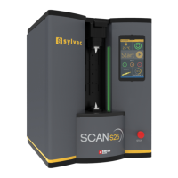
A special feature of this system is the projector screen which provides a five times magnified (nominal)
image of the component for SYLVAC-Scan 25 (x4 nominal for SYLVAC-Scan 50 and 50 Plus) and an
exact indication of the measurement point. The screen is used for component positioning during direct
measurement and can be used in programming as well as providing a visual check on component
alignment, focus and cleanliness.
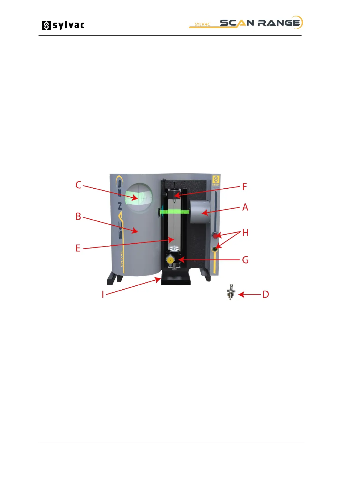
The main elements of the gauging system are the measurement device and the computer/controller.
Illumination Cover. Protects the illumination system.
Optics Cover. Protects the optical measurement system.
Projector Screen. Mounted on the optics cover.
Setting Master. Located in a holder on the top of the illumination cover.
Carriage. Supports the workholding
Tailstock. Adjustable to suit component length.
Headstock. Fixed position on the carriage.
Stop and Reset Switches. Stop switch cuts power to the traverse mechanisms. Reset switch re-
activates traverse mechanisms after E-Stop.
Emergency Stop Baseplate.
Note: If the emergency stop button is pressed during the measurement cycle, the power to the motor
control system will be removed. To reset the gauge ready for use after this condition has been used;
the emergency stop button should be un-latched before pressing the green “Reset button”. This will
return power to the control mechanisms.