4-2
Rev 2.2, 10/31/94
If you press and hold the SAVE switch without pressing LEAVE EDIT first, the 601 performs the
save operation (using the current program number) and returns you to where you were.
Caution
If the LOAD switch is flashing, this indicates that the current program
number is different than the program number that the edit buffer was
loaded from. If you press and hold the
SAVE switch, you will overwrite the
program number that is visible when you press
LEAVE EDIT.
4.1.3 Comparing Programs
You can compare the program in the edit buffer with the unedited version of the program.
Pressing the
COMPARE switch toggles the 601 between the edited and unedited versions of the
program. It is not possible to compare the edited program with any other program. The display
toggles between
OLd
and
CUrr
ent to remind you what you're listening to. Pressing any parameter
switch instantly returns you (and the outputs) to
CUrr
.
4.2 Rate of Change Parameter
In addition to the parameters visible on the front panel, many of the 601's parameters have a
rate-of-change parameter (
rt
) associated with them. The rate parameter affects how quickly the
parameter changes from its current value to its new value, either under direction of the front
panel or MIDI. In essence, the rate parameter (rt) affects how fast the knob can turn (the knob
is a "virtual knob" that represents a parameter that can be adjusted using the Wheel or via
MIDI). You can see which parameters have an associated rate parameter by referring to the
table in section C.3.1.
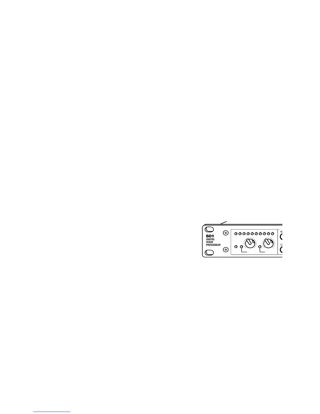
4.3 Input Level Control Block
This switch and control block sets the operating conditions
for the analog-inputs of the 601. The controls and indicators
operate as follows:
INPUT HEADROOM (DB) LED display indicates amount of headroom
remaining at the output of the A-D converters in
the 601. The display ballistics are peak reading;
the display should be interpreted as the absolute
amount of headroom remaining.
The numbered part of the display reads the higest
peak digital signal level of the two input channels
(left and right) after the digital gain control at the
input to the DSP section. The display can
(temporarily) indicate the signal level of the left or
right DSP channels via the
GLOBAL switch.
The
CLIP LED responds only to overload at the
output of the analog mic or line input amplifiers.
To maximize the dynamic range, set either of the
two input gain controls (
MIC or LINE) so that the
green 2 dB LED illuminates. The red
CLIP LED
should never illuminate.
N
CLIP4312 6 2
+4 -10 50
LINE
24 1848 36
0
IN / SYNC
DIGITAL
MIC
INPUT HEADROOM (dB)
INPUT LEVEL CONTROL
B