7-7
Rev 2.2, 10/31/94
7.4.3 Using the 601 as an A-D Converter
You can use the 601 as an analog-to-digital converter simply by using the analog input(s) and
the AES/EBU or S/PDIF output. There are, however, several caveats:
1. The clock accuracy specification stated in the AES/EBU standard is quite stringent In
applications requiring simultaneous digital sources (like a digital mixer or digital
multitrack recorder), the sample-rate clocks for every source should be phase-locked
(synchronized) to a common source. This is described in section 7.3.5.
2. The 601 has internal 44.1 kHz and 48 kHz clocks, which should be adequate for most
applications.
7.4.4 External Sample-Rate Clock
The 601 can be synchronized to an external clock signal via the AES/EBU or S/PDIF digital
inputs. From the front panel, select
CLCE
( in the global block), Apply the external clock signal
to either of the digital inputs. Avoid paralleling more than 2 inputs as loading of the clock
source becomes a problem. The sample-rate clock should be a dedicated AES/EBU signal
source.
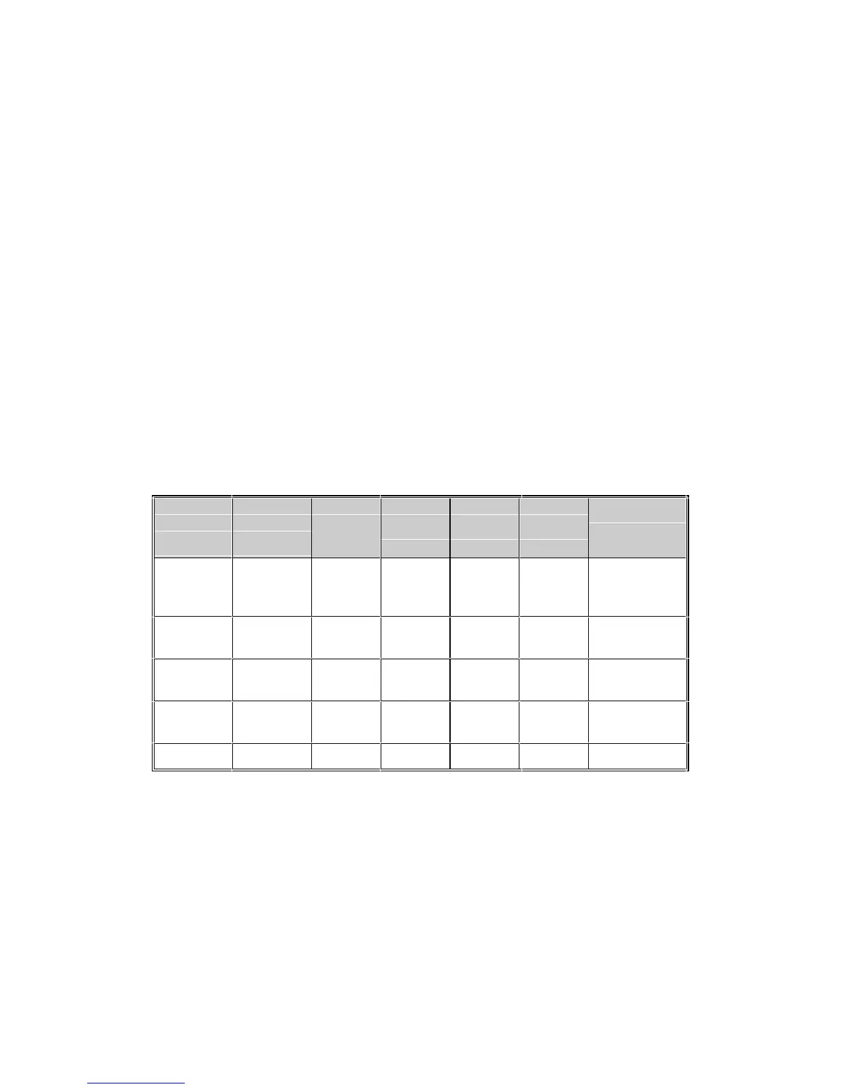
7.4.5 Input/Output/Clock Summary
The following table tabulates the various input/output/clock possibilities. See also section
4.8.1.
Input
Source
Setting
Input
LED
Glows
Digital
IN/SYNC
LED
Sample
Rate
Clock
Ref.
Clock
Setting
Notes
Analog Line or
Mic
off 44.1 kHz
or 48
kHz
internal
CLCI
Analog Line or
Mic
steady either external
CLCE
1, 2, 3, 5
Analog Line or
Mic
steady either external
CLCE
2, 3, 4, 5
Digital Digital
IN/SYNC
steady either external
CL--
1, 2, 3, 5
Any flashing either external
CLCE
3, 5
Notes (correspond to "Notes" column in previous table):
1. Connect the digital clock source to the digital input connector.
2. The source connected to the digital input supplies the sample-rate clock.
3. The
DIGITAL IN/SYNC LED flashes if there is no digital source, or if the digital data is faulty.
4. Connect the digital I/O connectors to another digital I/O processor.
5. The
DIGITAL IN/SYNC LED column shows the state of the DIGITAL IN/SYNC LED on the front
panel.