26
| Instructions for unloading on the site as well as installation and connection
I.3.3.1 Necessary mains power supply for Geniox units with cabinet/control system
Necessary mains power supply is printed on the unique machine card placed on the front of every unit (see example of
a machine card in chapter D.2.1).
I.3.3.2 Necessary overvoltage protection device, that leads lightning overvoltage to an
earth lead on a safe way.
The Installer and user must be aware of the fact that lightning strikes make a risk that requires installation of overvolt-
age protection devices to lead the lightning overvoltage to an earth lead in a safe way. Installer and user must take care
of this according to local statutory requirements.
I.3.4 Electrical connection of components and functions
External components and functions are delivered according to the order confirmation. Cable numbers appear from the
label inside or on the cabinet, and cable numbers appear from the wiring diagrams.
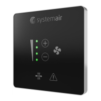
I.3.4.1 Connection of the Systemair Control Panel to the Corrigo E28 controller
The SCP panel is provided with 10 metres of cable. Demount the cable at the back of the Systemair Control Panel - pull
the cable through the cable entry in the cabinet - and remount the cable in the panel, or add more cable – up to 100 m
of cable between the Systemair Control Panel and the controller is possible. Place the Systemair Control Panel on the
outer side of the unit or on a wall.
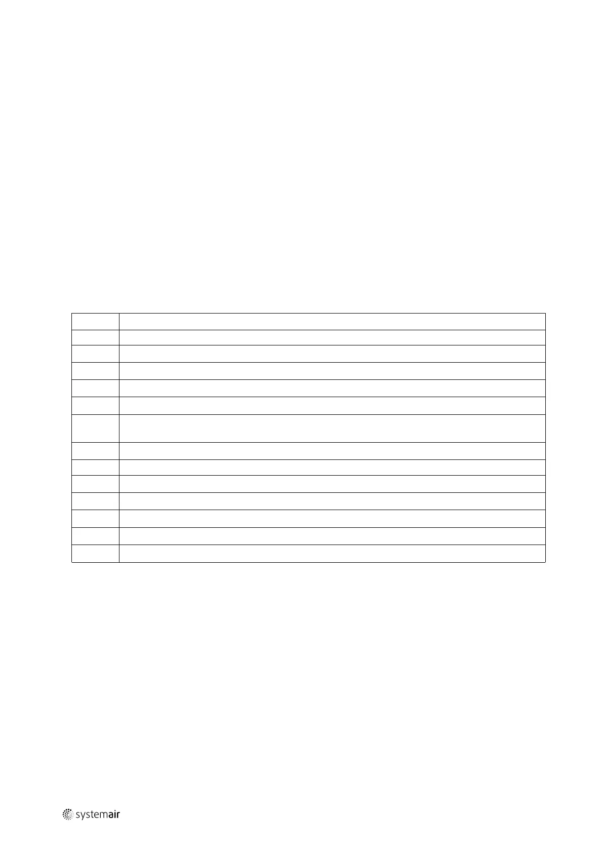
Position Description
1
Alarm button: Press for alarm list.
2
Alarm indicator: Flashing for unacknowledged alarm.
3
Write enable LED: Slow flashing indicates parameters can be changed.
4
OK button: Press to activate a selected menu/setting, if possible.
5
Button for clear: Abort a parameter setting or – if possible - restore the original value.
6
Right/left – and up/down buttons: Used for navigation up and down and to the right and left in the menu
tree. Up/down buttons are also used for increasing or decreasing values of parameters.
7
Holes for mounting
8
Terminal block
9
No cable on terminal 5 for software version 3.4 (illustrated with number 9 on the above drawing)
10
Brown cable on terminal 4 for software version 3.4 (illustrated with number 10 on the above drawing)
11
Yellow cable on terminal 3 for software version 3.4 (illustrated with number 11 on the above drawing)
12
White cable on terminal 2 for software version 3.4 (illustrated with number 12 on the above drawing)
13
Black cable on terminal 1 for software version 3.4 (illustrated with number 13 on the above drawing)
output |