Speed control for rotor and assembly of divided rotor |
9-2
9.1.2 Indication of operation mode via red and green LED as well as test of motor
The LED is in the cover of the cabinet.
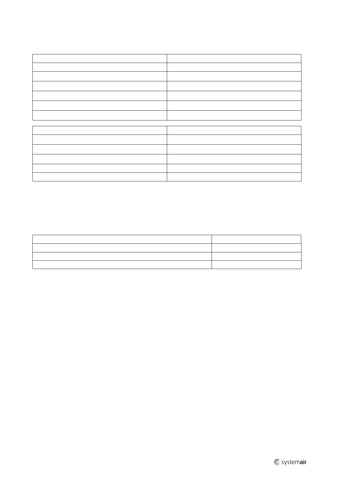
LED indication Value
No indication Power off
Green
Ordinary operation
Green – flashes Ready for operation
Green/redstrobe,slow Magnet on the rotor has activated rotor guard
Green/red strobe, fast
Restart sequence active
Red Rotor guard has not been activated
Number of red flashes in series Value
1
Output current limit
2
Over voltage
3
Under voltage
4
Failure in the controller
5
Communication failure
Restart of rotor:
• Switch off power and switch on power again
or
• Press the test button inside the cabinet
Table 3 Test of motor by checking the resistance in all 3 vindings
Motor sizes
Ohm
90TYD-S214-M 40Ω
120TYD-S214-M 18Ω
120TYD-S214-L 10Ω
Setting of constant speed:
• Set fourth DIP switch lever in position - ON
Test:
• Set fourth DIP switch lever in position – ON
• Press the test button
output |