Start-up, adjustments, use, commissioning and unit in hipernation |
35
measured by pressure transmitters. PI calculation in the controller continuously transmits the necessary revolutions for
the fans to the frequency converters to achieve the required pressure.
K.6.10.3 CO2-dependent air flow
The air flow is controlled by a CO
2
sensor. High CO
2
concentration is equal to higher air flow. Low CO
2
concentration is
equal to lower air flow. Based on the actual CO
2
level and a min/max level, the needed airflow is calculated. The speed
of each fan is adjusted via frequency converter. Terminals in the cabinet are available for connection of the sensor.
K.6.10.4 Humidity dependent air flow
The air flow is controlled by the humidity sensor. High humidity is equal to higher air flow. Low humidity is equal to low-
er air flow. Based on the actual humidity level and a min/max level the needed airflow is calculated. The speed of each
fan is adjusted via frequency converter. Terminals in the cabinet are available for connection of the sensor
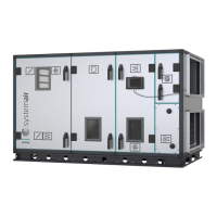
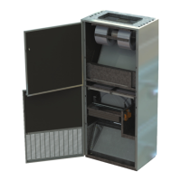
K.6.11 Cabinet
K.6.11.1 Integrated cabinet in units with control system
Cabinet is integrated in the unit behind an inspection door. Terminals are installed in the cabinet for all external compo-
nents. The number of terminals is always adapted to the individual order.
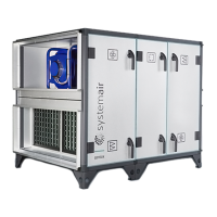
K.6.11.2 Cabinet placed on the unit with control system
The models with the cabinet on the unit are exclusively for indoor installation. Terminals are installed in the cabinet for
all external components. The number of terminals is always adapted to the individual order.
K.6.12 Temperature sensors
Four sensors are always delivered with each unit. See below where the sensors are placed;
• 1 sensor in the extract air, installed inside the unit
• 1 sensor in the outdoor air, installed inside the unit before the supply air filter on the cold side of the heat exchanger
• 1 sensor in the supply air to be placed in the supply air duct by the installer
• 1 sensor in the exhaust, installed inside the unit
K.6.13 Damper motors
Four different types of damper motors are available;
• On/off damper motor, without spring return function. Torque is 20 Nm and run time is 150 seconds
• Modulating damper motor, without spring return function. Torque is 20 Nm and run time is 150 seconds
• On/off damper motor, with spring return function. Torque is 20 Nm and run time is 150/16 seconds
• Modulating damper motor, with spring return function. Torque is 20 Nm and run time is 150/16 seconds
K.6.14 Filter guards
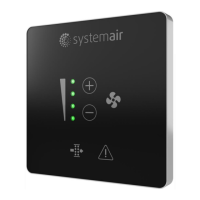
Filter guard over pre-filter and primary filter installed and connected to the controller for display of alarm when the me-
chanically set limit is exceeded. Filter alarm will be displayed on the Systemair Control Panel.
K.6.15 Room temperature sensors
One or two external room temperature sensors are available. The cabinet has been prepared with additional terminals
for connection of the room temperature sensors. The sensors are delivered without cable. The controller calculates an
average of the value from the 2 sensors as input for the control.
K.6.16 Frost protection
For the frost protection of the heating coil, the water temperature in the coil is transmitted to the controller by a tem-
perature sensor in a water return circuit of the coil. The controller always generates a signal to the valve motor that
keeps a sufficient flow of hot water to protect the coil against frost. This frost protection is also activated when the run-
ning mode is “off”.
If the water temperature falls below the set point temperature the fans stop, the dampers close, and an alarm is
activated.
output |