output |
Contents
R.4 Filters – always replace filters with new filters with the same characteristics to maintain SFP
value ................................................................................................................................. 43
R.4.1 Bag filters – the number of filters and sizes of frames ........................................................ 43
R.4.2 Panel filters – the number of filters and the sizes of the frames ............................................ 44
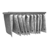
R.4.3 Bag filters ................................................................................................................ 44
R.4.4 Panel filters.............................................................................................................. 47
R.5 Changing the Internal Battery in the controller ............................................................................. 47
R.6 Other functions to maintain ..................................................................................................... 48
R.6.1 The unit................................................................................................................... 48
R.6.2 Dampers.................................................................................................................. 48
R.6.3 Rotary heat exchanger ............................................................................................... 50
R.6.4 Cross flow and counter flow exchanger .......................................................................... 51
R.6.5 Run-around heat exchanger......................................................................................... 52
R.6.6 Heating coil .............................................................................................................. 53
R.6.7 Plug fans ................................................................................................................. 54
R.6.8 Silencer................................................................................................................... 55
R.6.9 Outdoor air section .................................................................................................... 56
R.6.10 Heat pump unit ......................................................................................................... 56
S Instructions to enable adjustment and maintenance safely........................................................................ 57
S.1 Protective measures and additional protective measures................................................................ 57
S.1.1 Necessary protection measures prior to start-up .............................................................. 57
S.1.2 Safe adjustment and maintenance ................................................................................ 58
S.1.3 Personal protective equipment for maintenance staff – health and safety............................... 58
T The specifications of the spare parts to be used, when these affect the health and safety of operators ............... 58
T.1 Spare parts - Mechanical ......................................................................................................... 58
T.2 Spare parts - Electrical ............................................................................................................ 58
U Information on airborne noise emissions exceeding 70 dB(A) .................................................................... 58
Annex 1 Declaration of conformity with production number (in separate cover) ..............................................1-1
Annex 2 Technical data – unique data for every unit (in separate cover) ........................................................2-1
Annex 3 Spare part list (in separate cover) ..............................................................................................3-1
Annex 4 Assembly of base frame – height 118 mm for unit sizes 10 – 18.......................................................4-1
4.1 Base frame length 482 – 2564 [mm] Unit size 10 – 18 ..................................................................4-2
4.2 Base frame length 2582 – 4964 [mm] Unit size 10 – 18 ................................................................4-3
4.3 Base frame length 4982 – 6164 [mm] Unit size 10 – 18 ................................................................4-4
Annex 5 Assembly of base frame – height 118 mm for unit sizes 20 – 31.......................................................5-1
5.1 Base frame length 482– 2564 [mm] Unit size 20 – 31 ...................................................................5-1
5.2 Base frame length 2582 – 4964 [mm] Unit size 20 – 31 ................................................................5-2
5.3 Base frame length 4982 – 6164 [mm] Unit size 20 – 31 ................................................................5-3
Annex 6 Assembly of base frame – height 218 mm for unit sizes 10 – 18 ......................................................6-1
6.1 Base frame length 482– 2564 [mm] Unit size 10 – 18 ...................................................................6-1
6.2 Base frame length 2582 – 4964 [mm] Unit size 10 – 18 ................................................................6-2
6.3 Base frame length 4982 – 6164 [mm] Unit size 10 – 18 ................................................................6-4
Annex 7 Assembly of base frame – height 218 mm for unit sizes 20 – 31.......................................................7-1
7.1 Base frame length 482– 2564 [mm] Unit size 20-31 ....................................................................7-1
7.2 Base frame length 2582 – 4964 [mm] Unit size 20 – 31 ................................................................7-2
7.3 Base frame length 4982 – 6164 [mm] Unit size 20 – 31 ................................................................7-3
Annex 8 Installation of steel roof in the sizes 10 – 31.................................................................................8-1
8.1 Overview............................................................................................................................8-1
8.1.1 Mount rails. Units of size 10, 11, 12, and 14....................................................................8-1
8.1.2 Mount rails. Units of size 16 and units larger than size 16...................................................8-1
8.1.3 Roof overhang along the long sides of the unit ...............................................................8-2
8.1.4 Calculation of the overhang at the ends of the unit. Mount overhang profile – G1. ...................8-2
8.1.5 Foam bands between rails and roof plates – mount roof plates............................................8-3
8.1.6 Foam bands between roof plates .................................................................................8-3
8.1.7 Mount roof plates – some of them are overlapping by 2 ribs...............................................8-3
8.1.8 Mount overhang profile – G5 on the other end of the unit. .................................................8-3
8.1.9 Mount side profiles and corners along the edges of the roof to protect persons ......................8-3
8.1.10 Apply sealing on plate joints to ensure water resistance. ...................................................8-3
Annex 9 Speed control for rotor and assembly of divided rotor ....................................................................9-1
9.1 Speed control ......................................................................................................................9-1
9.1.1 Selection of correct signal via the 8DIP switch levers ........................................................9-1
9.1.2 Indication of operation mode via red and green LED as well as test of motor..........................9-2
9.1.3 Copy of the label with information about connection of cables............................................9-3
9.2 Assemble the Systemair casing for Geniox 22, Geniox 24 and Geniox 27 ..........................................9-3
9.3 Assemble divided rotor for Geniox 29 and Geniox 31....................................................................9-4
 Loading...


