TAC 2112, Manual Installation
5:8(
10
), 0-004-7459-3 (GB) 1999-08-01, TAC AB
Cable lengths
The following applies when the 24 V transformer is placed by the
TAC 2112:
The cables to G, G0 and other terminal blocks on TAC 24 V actuators
must not exceed 50 m in length, and shall have a minimum cross-
sectional area of 0,8 mm
2
. If the cables exceed 50 m in length, the
minimum cross-sectional area is 1,5 mm
2
. The same requirements
apply for cables connected to KC3, K5 and K6.
Cables connected to the terminal blocks KC1, K1, K2, KC2, K3, and
K4, must not exceed 100 m in length, and shall have a minimum
cross-sectional area of 1,5 mm
2
.
Cables leading to the controller should be fixed by stapling or as such.
Cables connected to terminal block types B, U, and X must not
exceed 200 m, and shall have a minimum cross-sectional area of
0,5 mm
2
.
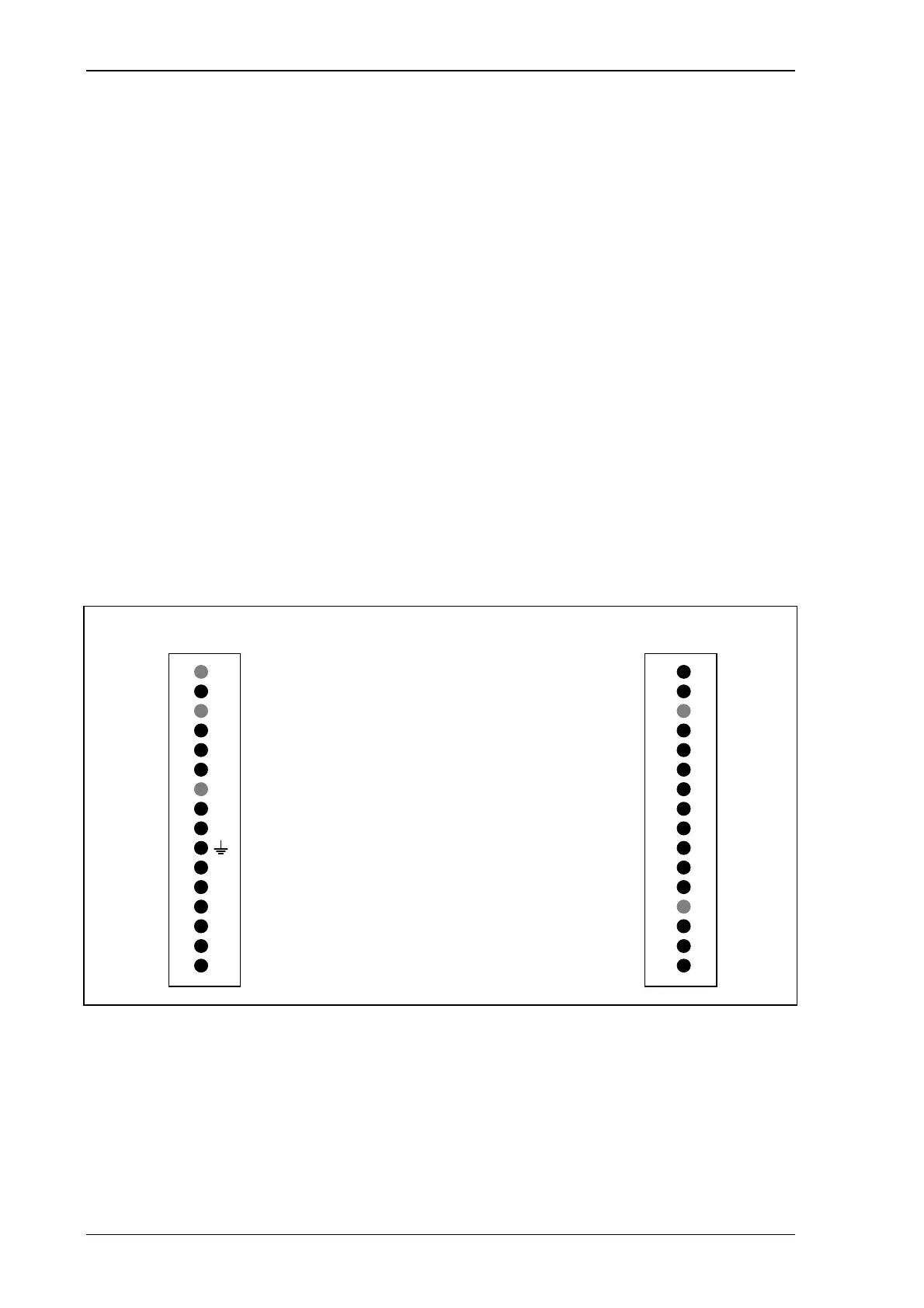
Terminal blocks
The location of the terminal blocks in the back of the controller can
be seen in the figure below.
LR
16
Y1
15
Y2
14
13
KC3
12
K5
11
K6
9
G
8
G0
7
6
KC1
5
K1
4
K2
3
KC2
2
K3
1
K4
M
M
U1
U2
U3
M
B1
M
B2
B3
B4
M
U4
X1
X2
M
10
16
15
14
13
12
11
9
8
7
6
5
4
3
2
1
10
Output, outdoor temp. signal
Common to K5 and K6
Output, open heating valve
Output, close heating valve
24 V AC, phase
24 V AC, zero
Safety ground
Common to K1 and K2
Output, pump control
Output, morning heating
Common to K3 and K4
Output, buzzer alarm
Output, weekly program 2
Measurement neutral
Input, SPC signal
Input, pump alarm
Supply temperature
Outdoor temperature
Reference temperature
Return temperature, heating
Input, extended daytime op.
Input, forced night setback
Measurement neutral
Measurement neutral
Measurement neutral
Measurement neutral
Measurement neutral
Terminal blocks in the back of the controller