Taco® SKV
14
302-365, Effective: June 5, 2017
© 2017 Taco, Inc.
8.3.5 Motor Connection
DANGER: INDUCED VOLTAGE! Run out-
put motor cables from multiple adjustable
frequency drives separately. Induced voltage
from output motor cables run together can
charge equipment capacitors even with the
equipment turned off and locked out. Failure
to run output motor cables separately could
result in death or serious injury.
• For maximum wire sizes, see “17.1 Power-depen-
dent Specifications” on page 75.
• Comply with local and national electrical codes for
cable sizes.
• Motor wiring knockouts or access panels are pro-
vided at the base of IP21 and higher (NEMA1/12)
units
• Do not install power factor correction capacitors
between the adjustable frequency drive and the
motor
• Do not wire a starting or pole-changing device
between the adjustable frequency drive and the
motor.
• Connect the 3-phase motor wiring to terminals 96
(U), 97 (V), and 98 (W).
• Ground the cable in accordance with grounding
instructions provided.
• Follow the motor manufacturer wiring requirements
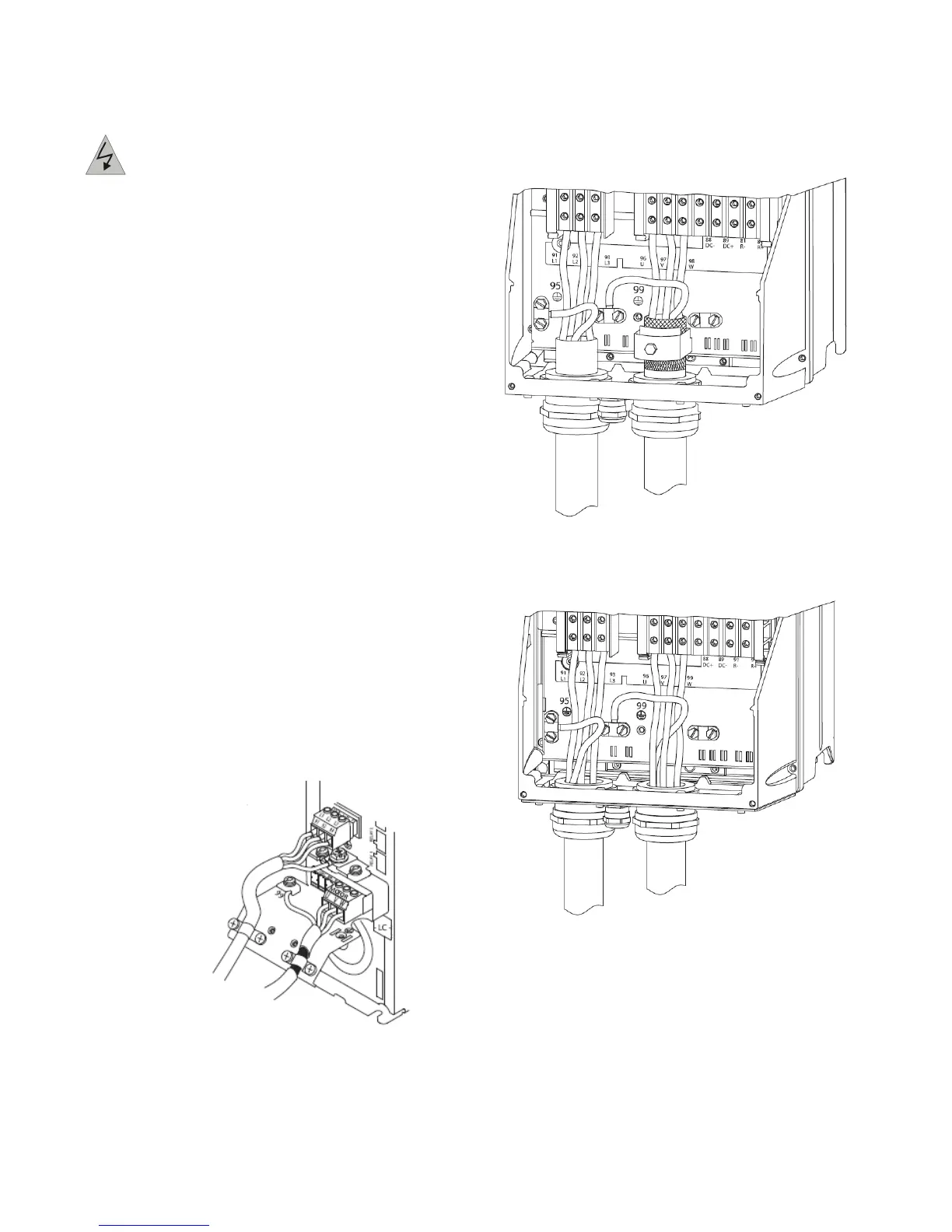
The three following figures represent line power input,
motor, and grounding for basic adjustable frequency
drives. Actual configurations vary with unit types and
optional equipment.
Figure 8-8: Motor, Line Power and Ground Wiring
for A-Frame Sizes
Figure 8-9: Motor, Line Power and Ground Wiring
for B-Frame Sizes and Above Using Shielded
Cable
Figure 8-10: Motor, Line Power and Ground
Wiring B-Frame Sizes and Above Using
Shielded Cable or Conduit
8.3.6 AC Line Power Connection
Size wiring based upon the input current of the adjustable
frequency drive.
• Comply with local and national electrical codes for
cable sizes.
• Connect 3-phase AC input power wiring to terminals
L1, L2, and L3 (see Figure 8-11).