Taco® SKV
41
302-365, Effective: June 5, 2017
© 2017 Taco, Inc.
12.3 Balancing Procedure
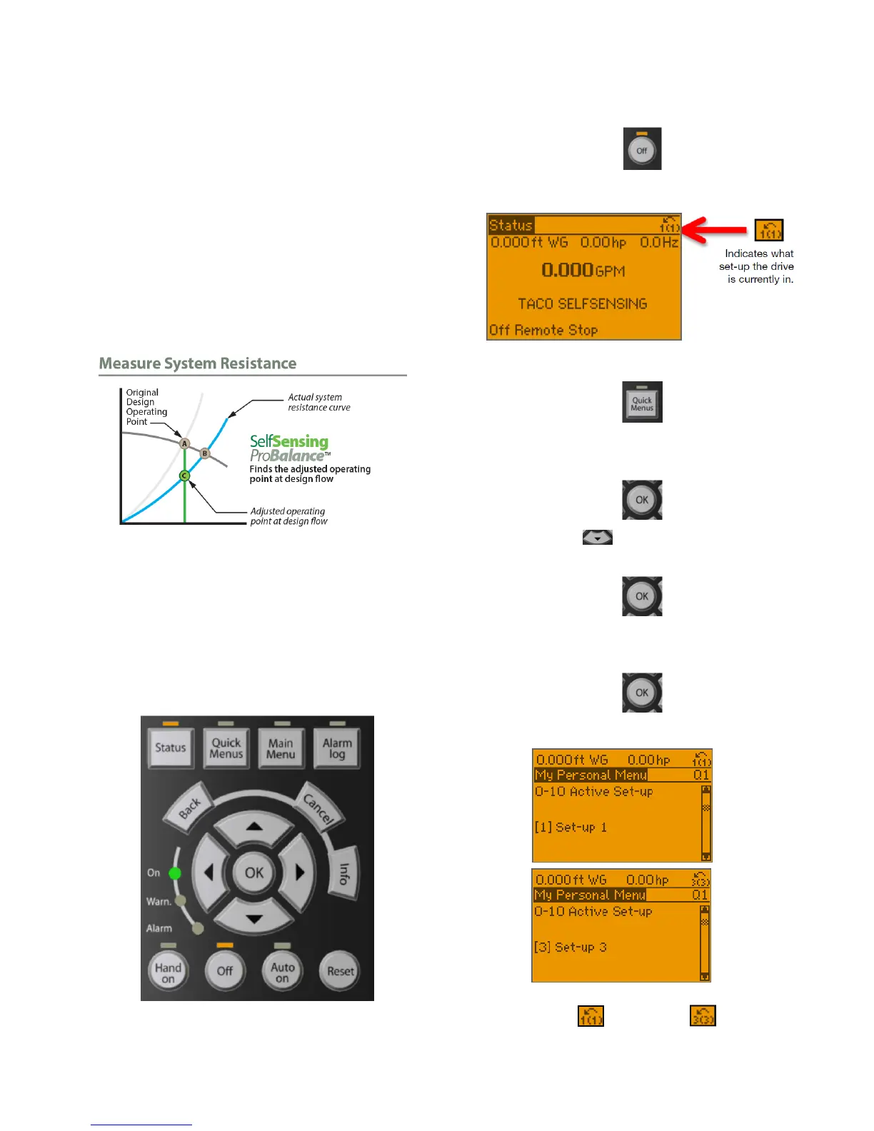
12.3.1 Measure System Resistance
Figure 12-4 shows a typical system response at startup.
Point A is programmed at the factory per the specifica-
tion/equipment schedule and the pump is set to stay on
the control curve shown in Figure 12-1. However, pumps
are typically oversized due to safety factor. Since the
actual system resistance is too low for the pump to oper-
ate at Point A, after it reaches its max speed (typically
60hz), the pump will 'run out' to the right on the 60hz
curve to Point B.
Figure 12-4: Measure System Resistance
The following procedure shows how to measure the
actual system resistance at the intended design flow.
(Point C) This point is used later to reprogram the pump
to operate along the adjusted control curve shown in
Figure 12-3.
1.Ensure the system is filled and all valves are set to
100% open.
2.To navigate on the keypad use the [OK] and
[ARROW] buttons shown below.
3.Press the [Off] Button.
4.Ensure the drive is in the set-up you ordered.
5.Press the [Quick Menus] button.
6.Press the [OK] button to enter “My Personal
Menu.”
7.Scroll down to Parameter 0-10 Active Set-up
and press OK.
8.Change Active Set-up from “Set-up 1” to “Set-up 3”
and press OK.
a.Parameter 0-10 Active Set-up.
b.You will know the change has happened when
you see change to .
Before
After