Taco® SKV
78 302-365, Effective: June 5, 2017
© 2017 Taco, Inc.
APPENDIX A: SET-UP FOR STANDBY PUMP ALTERNATION
This section describes how to alternate Taco SKV pump units based on elapsed time and how to configure the standby
pump to energize in the event that the duty pump fails.
A.1 Overview
Two identical drives are used; one installed on each pump. One drive is configured as the “lead” drive and the other as
the “standby” drive, but both drives participate equally in the alternation. The “lead” drive is the drive that controls the
alternation process. If one drive enters an alarm condition, the other automatically assumes operation. Alternation
attempts do not occur when one drive is in alarm.
This system requires one set of dry contacts for start/stop. Twenty-four VDC control voltage from both drives is wired to
the lead drive’s relay 1. If the lead drive’s control circuitry is working, it supplies power. If the lead drive cannot provide
control voltage, the standby drive automatically assumes control.
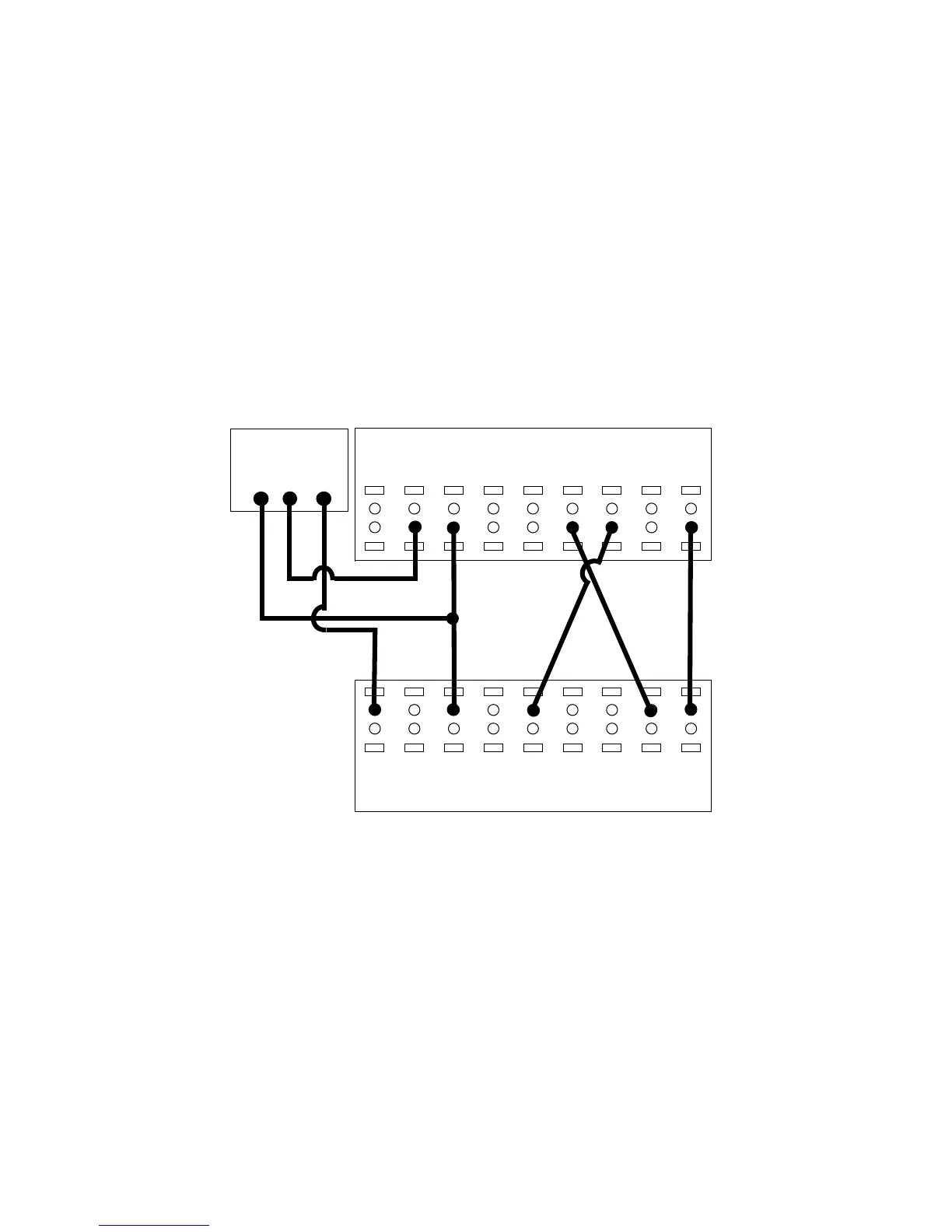
Figure A-1: Wiring for 2x0 Pump Alternation
No external monitoring is needed. Pump alternation is controlled by the active set-up of each drive. The active set-up is
controlled by the lead drive.
• Under normal conditions, the lead drivechanges its active set-up based on the time delay specified in timer 0 by
parameter setting 13–20.0.
• When the lead drive is operating normally in set-up 1, its digital output 29 is high. This state puts the standby drive
into set-up 2.
• When the lead drive is operating normally in set-up 2, its digital output 29 is low. This state puts the standby drive
into set-up 1.
• If the lead drive encounters an alarm condition or loses power, its digital output 29 is low. This state puts the
standby drive into set-up 1, allowing it to take over operation.
• If the standby drive encounters an alarm condition or loses power, its digital output 27 is low. This condition causes
the lead drive to move into set-up 1, allowing it to take over operation.
12
+24V
13
+24V
18
D IN
19
D IN
27
D IN
29
D IN
32
D IN
33
D IN
20
COM
I/O Digital
01
COM
Relay 1
02
NO
03
NC
Drive 1
12
+24V
13
+24V
18
D IN
19
D IN
27
D IN
29
D IN
32
D IN
33
D IN
20
COM
I/O Digital
Drive 2