Taco® SKV
10
302-365, Effective: June 5, 2017
© 2017 Taco, Inc.
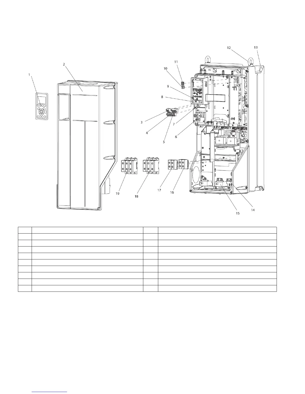
Figure 8-2: Exploded View B and C Sizes
8.2 Electrical Installation
This section contains detailed instructions for wiring the adjustable frequency drive. The following tasks are described.
• Wiring the motor to the adjustable frequency drive output terminals
• Wiring the AC line power to the adjustable frequency drive input terminals
• Connecting control and serial communication wiring
• After power has been applied, checking input and motor power; programming control terminals for their intended
functions
1 LCP 11 Relay 2 (04, 05, 06)
2 Cover 12 Lifting ring
3 RS-485 serial bus connector 13 Mounting slot
4 Digital I/O and 24 V power supply 14 Grounding clamp (PE)
5 Analog I/O connector 15 Cable strain relief / PE ground
6 Cable strain relief / PE ground 16 Brake terminal (-81, +82)
7 USB connector 17 Load sharing terminal (DC bus) (-88, +89)
8 Serial bus terminal switch 18 Motor output terminals 96 (U), 97 (V), 98 (W)
9 Analog switches (A53), (A54) 19 Line power input terminals 91 (L1), 92 (L2), 93 (L3)
10 Relay 1 (01, 02, 03)