Taco® SKV
35
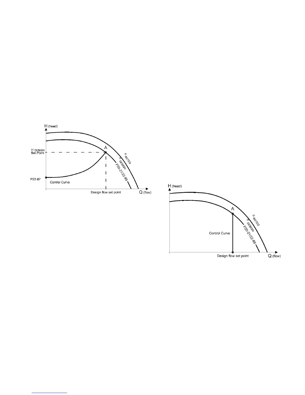
10.3 Variable Flow Control (Flow
Compensation)
Under Variable Flow Control (otherwise known as Flow
Compensation mode), the controller is set to control the
pump speed according to a ‘control curve’ between max
and min flow (see Figure 10-1 below). This mode should
be used for system distribution pumps. It is widely recog-
nised that fitting a differential pressure sensor at the most
remote load, across the supply piping and return piping
encompassing the valve & coil set, is the benchmark
scheme for energy efficiency.
Figure 10-1: Variable Flow Graph
Control
Head
SelfSensing pumps can replicate this control without the
need for the remote sensor. As the flow required by the
system is reduced, the pump automatically reduces the
head developed according to the pre-set control curve. In
other words, the pump follows the control curve.
It is often found that using a remote differential pressure
sensor to sense the pressure across a remote load could
theoretically result in loads close to the pump being
under-pumped. The situation would be where the load at
a loop extremity is satisfied and the control valve closes
while a load close to the pump needs full flow. The proba-
bility of this occuring is remote but it is possible. One
answer to this is to move the sensor closer to the pump
(two-thirds out in the system is a popular recommenda-
tion) although physically re-positioning the sensor at a
commissioning stage can be a costly exercise. With Self-
Sensing pump control it is possible to replicate the mov-
ing of a sensor by increasing the Control Head setting.
The design duty head and flow of the pump (provided at
time of order) is shown as point ‘A’ in Figure 10-1 below.
It is not always the case that the design duty point
required will fall on the maximum speed of the pump and
in the majority of cases (as shown in Figure 10-1 above)
it will be at a reduced speed.
302-365, Effective: June 5, 2017
© 2017 Taco, Inc.
The pump will be supplied with point ‘A’ set as the design
duty point provided at the time of order and the minimum
head at zero flow (Control Head) will be set as 40% of the
design head ‘H
DESIGN
’ as the default.
To change the control curve from the factory settings, fol-
low the startup procedures in “Appendix B: On-site Drive
Mounting to Wall or Pump” on page 83.
10.4 Constant Flow Control
SelfSensing pumps can be configured to maintain a con-
stant pump flow in a system. This control setting is ideal
for primary systems such as boiler or chiller loops that
require a constant flow.
10.4.1 For Central Plant, Constant Flow
Boiler/Chiller
If this pump was ordered for a central plant constant flow
boiler/chiller, you do not need to go through the balancing
procedures below. Ensure the drive is already in Set-up 3
(SelfSensing Constant Flow Mode) and is therefore
already self-balancing.
Figure 10-2: Constant Flow Graph
10.4.2 Settings for Constant Flow Control
To set the pump to constant flow mode and adjust the
flow rate, follow steps 1-12 in section 12.3.1.