Taco® SKV
23
302-365, Effective: June 5, 2017
© 2017 Taco, Inc.
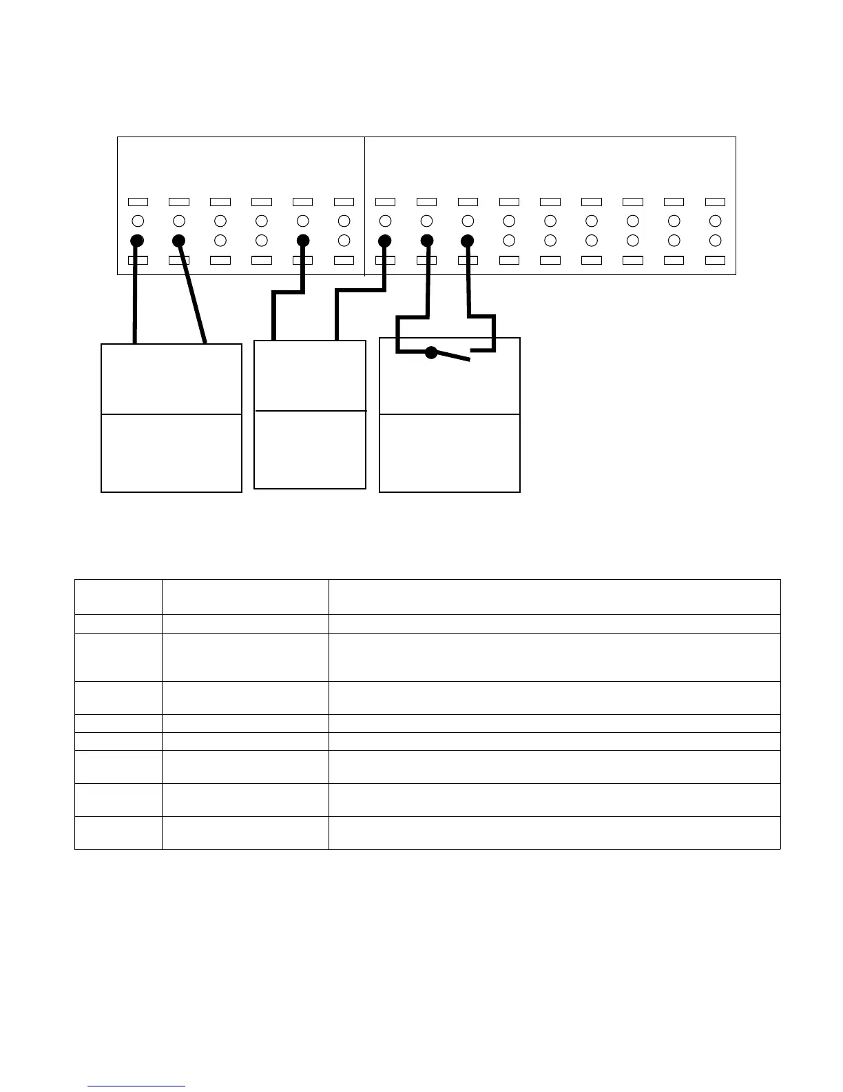
The following wiring scheme is used with Set-up 4 as shown in “10.1 SelfSensing Description” on page 34.
Figure 8-22: Terminal Wiring for 0–10V Sensor
39
COM
42
AOUT
50
+10V
53
A IN
55
COM
54
A IN
12
+24V
13
+24V
18
D IN
19
D IN
27
D IN
29
D IN
32
D IN
33
D IN
20
COM
I/O Analog I/O Digital
COM
AI
Unit Receiving
Analog Output
[6-50]
[137] Speed*
4-20 mA
* factory default
Starting/Stopping
Controller
[5-10]
[8] Start*
Start: Closed
* factory default
AO
+24V
0-10V
Transducer
[Group 6-]
[Group20-]
(See Table)
Set A54=U
(Optional)
To configure the controller for closed loop control based on the input from an external transducer, use the following
parameters:
Table 4: Settings for a Wired Sensor for Input
* To use AI 53, set parameters 6–14, 6–15, 6–17 and set 20–00 to “Analog Input 53.”
To set up the controller with a transducer that is intended for external monitoring, as opposed to feedback to the con-
troller, set the following parameters:
Parameter
number
Description Set to
0–10 Active Set-up For wired pressure transducer, choose Set-up 4.
6-24* Terminal 54 Low Ref./Feedb.
Value
Minimum transducer input value. For example, for a 0–100 PSI transducer, set to
0. For live 0 function set feedback to 1V or 10 PSI. Note: Live 0 does not work if
minimum is set to 0.
6-25* Terminal 54 High Ref./Feedb.
Value
Maximum transducer input value. For example, for a 0–100 PSI transducer, set to
100.
6-27* Terminal 54 Live Zero Enabled
20-00 Feedback 1 Source Analog Input 54*
20-12 Reference/Feedback Set as appropriate for application. For example, set to PSI when using a pressure
transducer. The default value for this setting is PSI.
20–13 Minimum Reference/Feed-
back
Minimum transducer input value. For example, for a 0–100 PSI transducer, set to
0 PSI.
20–14 Maximum Reference/Feed-
back
Maximum transducer input value. For example, for a 100 PSI transducer, set to
100 PSI.