Taco® SKV
29
302-365, Effective: June 5, 2017
© 2017 Taco, Inc.
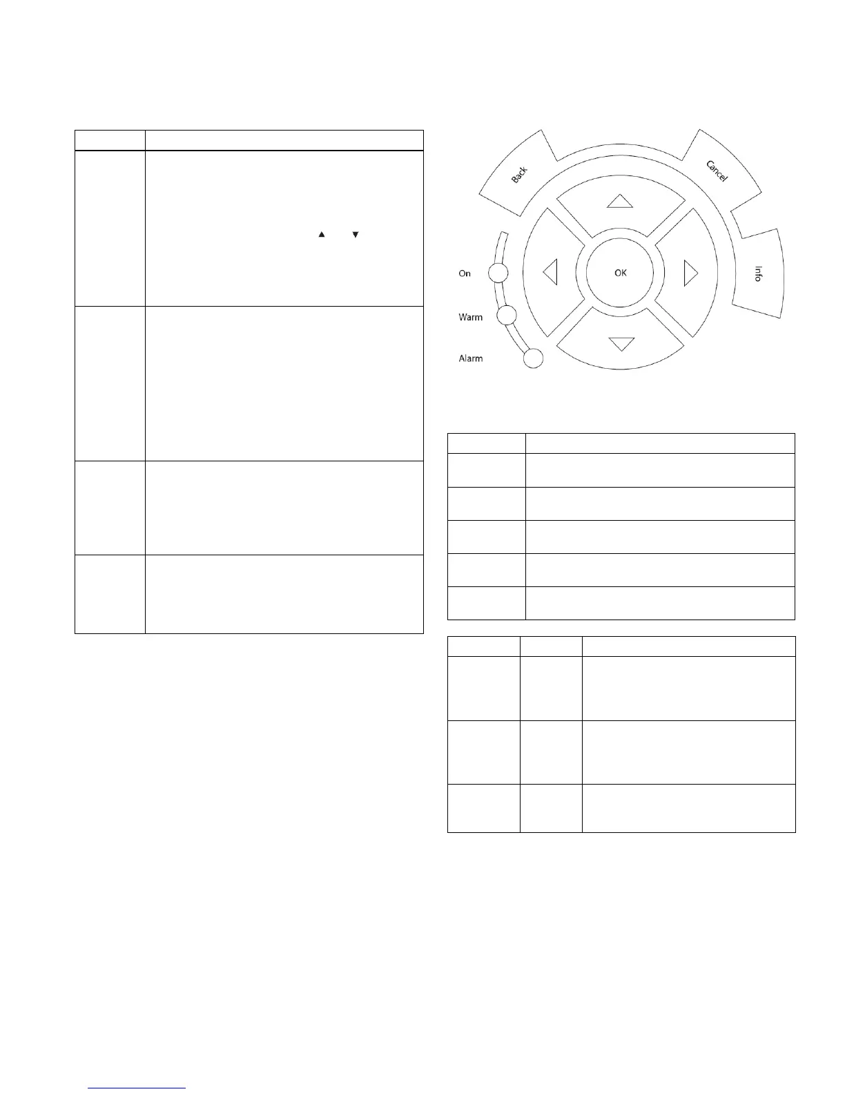
Navigation Keys
Navigation keys are used for programming functions and
moving the display cursor. The navigation keys also pro-
vide speed control in local (hand) operation. Three
adjustable frequency drive status indicators are also
located in this area.
Figure 9-3: Navigation Keys
Key Function
Status Press to show operational information.
• In Auto mode, press and hold to toggle between
status readout displays.
• Press repeatedly to scroll through each status
display.
• Press and hold [Status] plus [ ] or [ ] to adjust
the display brightness.
• The symbol in the upper right corner of the dis-
play shows the direction of motor rotation and
which set-up is active. This is not programmable.
Quick
Menu
Allows access to programming parameters for ini-
tial set-up instructions and many detailed applica-
tion instructions.
• Press to access Q2 Quick Set-up for sequenced
instructions to program the basic adjustable fre-
quency drive set-up.
• Press to access Q3 Function Set-ups for
sequenced instructions to program applications
• Follow the sequence of parameters as pre-
sented for the function set-up.
Main Menu Allows access to all programming parameters.
• Press twice to access top level index.
• Press once to return to the last location
accessed.
• Press and hold to enter a parameter number for
direct access to that parameter.
Alarm Log Displays a list of current warnings, the last 10
alarms, and the maintenance log.
• For details about the adjustable frequency drive
before it entered the alarm mode, select the alarm
number using the navigation keys and press [OK].
Key Function
Back Reverts to the previous step or list in the menu
structure.
Cancel Cancels the last change or command as long as
the display mode has not changed.
Info Press for a de!nition of the function being dis-
played.
Navigation
Keys
Use the four navigation arrows to move
between items in the menu.
OK Use to access parameter groups or to enable a
choice.
Light Indicator Function
Green ON The ON light activates when the
adjustable frequency drive receives
power from AC line voltage, a DC bus
terminal, or an external 24 V supply.
Yellow WARN When warning conditions are met, the
yellow WARN light comes on and text
appears in the display area identifying
the problem.
Red ALARM A fault condition causes the red alarm
light to flash and an alarm text is dis-
played.