Taco® SKV
5
302-365, Effective: June 5, 2017
© 2017 Taco, Inc.
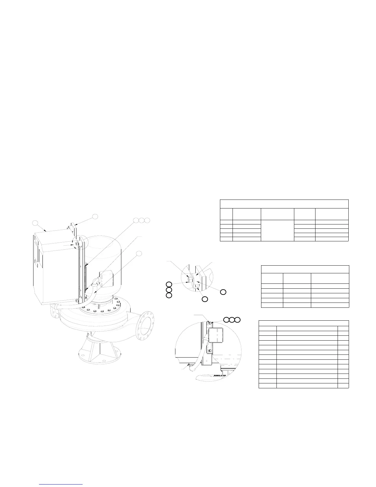
Figure 7-1: VFD Mounting to Pump
ALTERNATIVE BRACKET VIEW
SKV or SKS BOM Assembly
ITEM # DESCRIPTION QTY
1 VFD 1
2 BAR BRACKET 2
3 WIRE HARNESS - MOTOR POWER 1
4 VIBRATION ISOLATION MOUNT 4
5 SAFETY STRAP 4
6 NUT (VFD) 4
7 LOCK WASHER (VFD) 4
8 WASHER (VFD) 4
9 SCREW (MOTOR) 4
10 LOCK WASHER (MOTOR) 4
11 WASHER (MOTOR) 4
N/A "LOCTITE" (242; P/N 24231) N/A
TORQUE REQUIREMENTS
ALL TORQUE VALUES ARE +/- 15%
SIZE
"A"
MOTOR POWER
WIRES TO VFD
(In-lbs / Nm)
"B"
VIBRATION MOUNT
TO BAR BRACKET
(In-lbs / Nm)
VIBRATION
MOUNT
THREAD
SIZE
"C"
VFD NUT TO
VIBRATION MOUNT
(Ft-lbs / Nm)
A5 5 / 0.6
SEE NOTE #7
M6 X 1 4.3 / 5.8
B1 16 / 1.8 M8 X 1.25 11.3 / 15.3
B2 40 / 4.5 M8 X 1.25 11.3 / 15.3
C1 89 / 10 M8 X 1.25 11.3 / 15.3
C2 124 / 14 M8 X 1.25 11.3 / 15.3
TORQUE REQUIREMENTS
ALL TORQUE VALUES ARE +/- 15%
MOTOR
SIZE
BOLT SIZE
"D" MOTOR BOLT
TO BAR BRACKET
(FT-LBS / NM)*
143-145 5/16 X 18 11.5 / 15.6
182-215 3/8 X 16 20 / 27
254-286 1/2 X 13 49 / 66
324-365 5/8 X 11 98 / 133
404-449 3/4 X 10 173 / 235
1
2
9
3
10 11
"D"
A
DETAIL A
SCALE 1 : 4
"C"
"B"
APPLY LOCK TIGHT
BAR SIDE ONLY
6
7
8
4
5
"D"
9
"A"
10 11
1.Items specified on this drawing are specifically for the SKV or SKS product series.
2.Assemble safety strap onto isolation mount stud to produce orientation shown in the assembly drawing.
3.Apply 'Loctite' to isolation mount stud threads (1 place) on all 4x parts.
4.Assemble threaded stud with 'Loctite' into bar bracket until surfaces are in contact without gaps.
5.Use strap wrench for isolation mounts. Screw mount into bar bracket (#2) until the rubber face is flush against the
bar. Torque the mount 1/4 of a full turn.
6.Support VFD & assemble onto 4 isolation mounts simultaneously, assemble lockwashers & nuts, torque to specifi-
cations "C", remove VFD support.
7.Assemble the motor so the feet are angled between 22.5° to 45° offset from the flanges, as shown below.
8.Assemble the motor so the VFD and motor conduit box are hanging over the outlet volute.
9.* = all "D" bolt connections are SAE J429 grade #2 steel - nickel plated.