TB8100 Installation and Operation Manual Functional Description 59
© Tait Electronics Limited June 2005
1. The PA receives a PA_KEY_COAX signal instructing it to key up.
This is a DC signal on the coaxial cable that goes from reciter to PA.
2. The PA microprocessor turns the 10V power rail on, and then waits
for 20-30ms for the regulator to stabilise the power.
3. The microprocessor sets the power level.
4. The microprocessor provides its usual ramping signal. This has the
form of a raised cosine.
PMU Hysteresis
Mode
Hysteresis mode is the first means of reducing current consumption in the
PMU. It requires a PMU standby power supply card and is not available if
the PMU’s auxiliary power output is on.
While the PMU DC converter is highly efficient for output currents in the
range of 1-15A, it is not efficient for low output currents. This is mainly due
to the current drive requirements for the heavy-duty switching FETs (field
effect transistors).
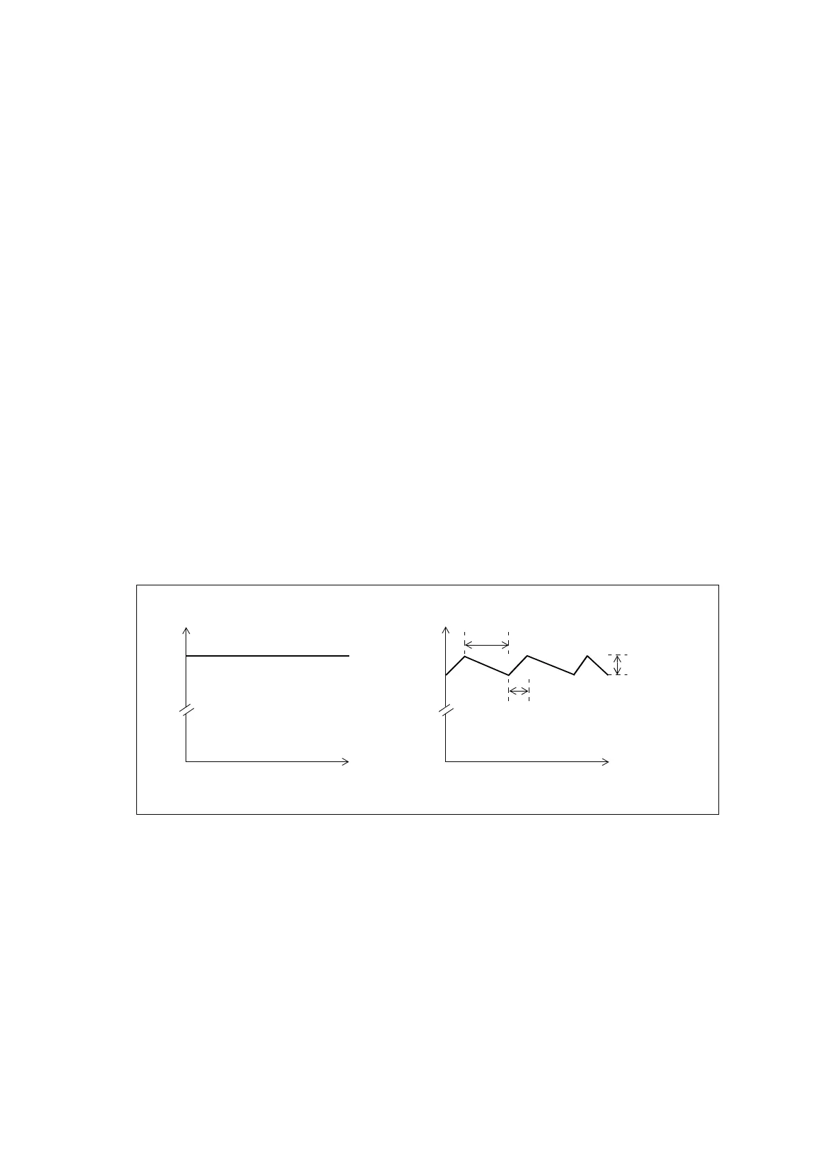
Hysteresis mode resolves this issue by setting the output voltage to swing
between two fixed levels. This allows the FETs drive signal to be turned off
for periods of time. The FET off time is dependent on the load current
drawn. Figure 4.7 on page 59 illustrates the output voltages for the PMU
DC converter in both normal and Hysteresis modes.
You can confirm whether the PMU is in Hysteresis mode by connecting an
oscilloscope to the PMU’s 28V output power connector. You should see the
voltage ripple.
Hysteresis mode is used only when the base station is not transmitting. The
ripple generated by Hysteresis mode does not degrade the performance of
the receiver. However, when the base station is transmitting, Hysteresis
mode is turned off because the PA should never transmit with the ripple
voltage present.
Figure 4.7 DC converter output voltages in PMU operation modes
Time
Voltage
27.9
Time
Voltage
27.9
Normal mode Hysteresis mode
27.5
FET switches OFF once upper
threshold reached
Output voltage
ripple
(hysteresis voltage)
FET switches ON once lower
threshold reached

 Loading...


