SERVICE PROCEDURES
SERVICE PROCEDURES
34 • On-Demand Water Heater Service Handbook for 240, 340 & 540 Condensing Models
12. The gas supply pressures should be
within the following ranges:
•
Natural Gas: 4 to 10.5 inches W.C.
•
Propane: 8 to 14.0 inches W.C.
13. Subtract your static supply gas
pressure (step 11) from your dynamic
supply gas pressure (step 9). This will
be your pressure drop.
14. If the pressure drop is more than 1
inch W.C., there may be insufficient
gas supply, incorrectly sized gas
line, or incorrectly sized gas
regulator. NOTICE: In Canada, do
not exceed the maximum allowable
pressure drop permitted by B149.1.
15. Remove the manometer.
16. Install the screw into the gas
pressure port on the gas inlet
(hand tight).
WARNING! Ensure that there are
no gas leaks. Failure to prevent gas
leaks can result in an explosion,
severe injury, or death.
17. Turn power to the water heater on.
Checking and
Manifold Gas
Pressure
Complete the following procedures
ONLY if you have been instructed
to do so by the Technical Service
Department. Incorrect adjustment
may result in carbon monoxide
poisoning.
NOTICE:
Incorrect adjustment may damage
the water heater and/or shorten
its lifespan. Therefore, changing
the manifold pressure is not
recommended unless there are very
strong reasons to do so (e.g., high
elevation installations).
1. Verify that the gas supply pressure
is within the correct operating
range when the heater fires at
maximum combustion. (Incorrect
gas supply pressure will affect the
gas manifold pressure.)
2. Ensure that the unit is not in operation.
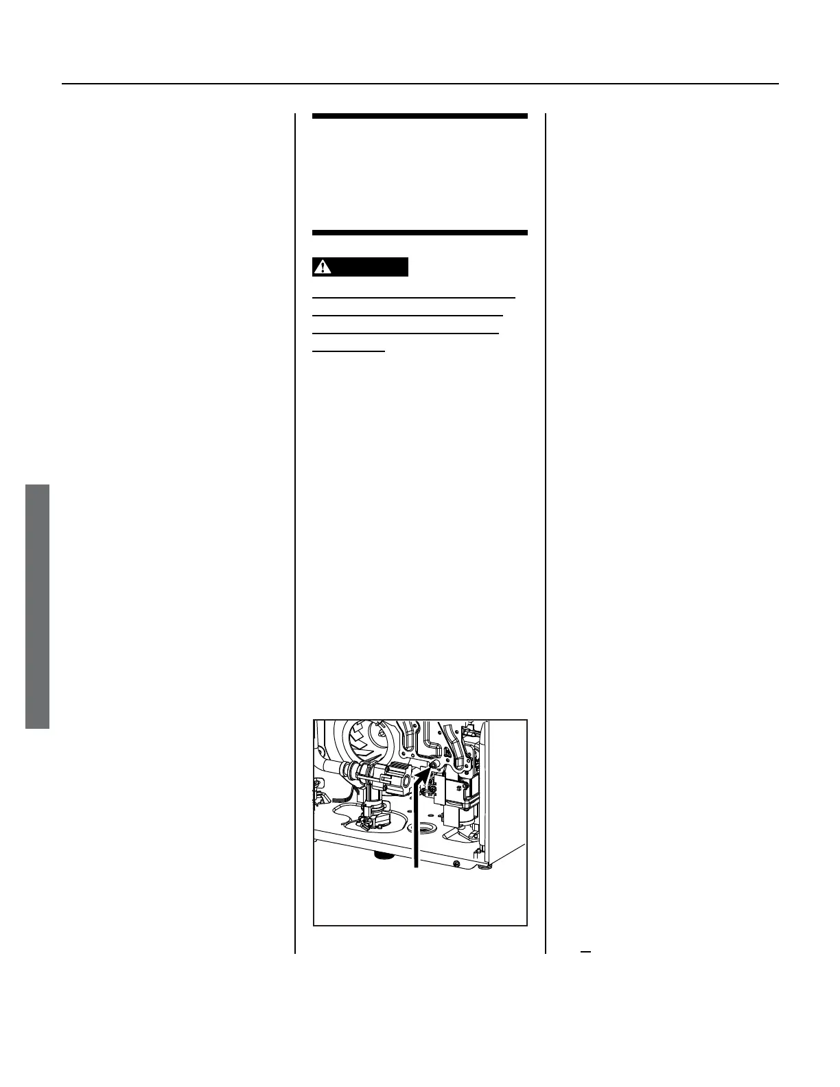
3. Remove the screw from the
manifold port (Figure 22).
4. Connect a manometer to the
manifold port using a tube. Ensure
that this connection is secure
enough to prevent a gas leak.
5. Run water (preferably 3.5 GPM
or more) to activate operation.
It is suggested that you draw a
large amount of flow to prevent
overheating during maximum
burn. If presence of a gas leak is
detected, immediately shut off the
unit and inspect the tube/manifold
connection. Otherwise, proceed to
the next step.
6. Check the manifold gas pressures:
•
To check the manifold gas
pressure during maximum
combustion, press and hold the
“MAX” button on the computer
board (Figure 20 or Figure 21, page
33).
•
To check the manifold pressure
during minimum combustion,
press and hold the “MIN” button
on the computer board (Figure 20
or Figure 21, page 33).
•
The desired pressures are listed
in the “Specifications” section.
(See page 4).
7. When you are finished, turn off
water flow or turn power to the
water heater off.
8. Remove the manometer tube, then
replace the port screw.
Complete the next step ONLY
if you have been instructed to
do so by the Technical Service
Department.
9. IF the manifold pressures do not
The p of the arrow indicates
the locaon of the manifold port.
Remove screw, then aach tube.
Figure 22.
 Loading...


