TROUBLESHOOTING
TROUBLESHOOTING
30 • On-Demand Water Heater Service Handbook for 240, 340 & 540 Condensing Models
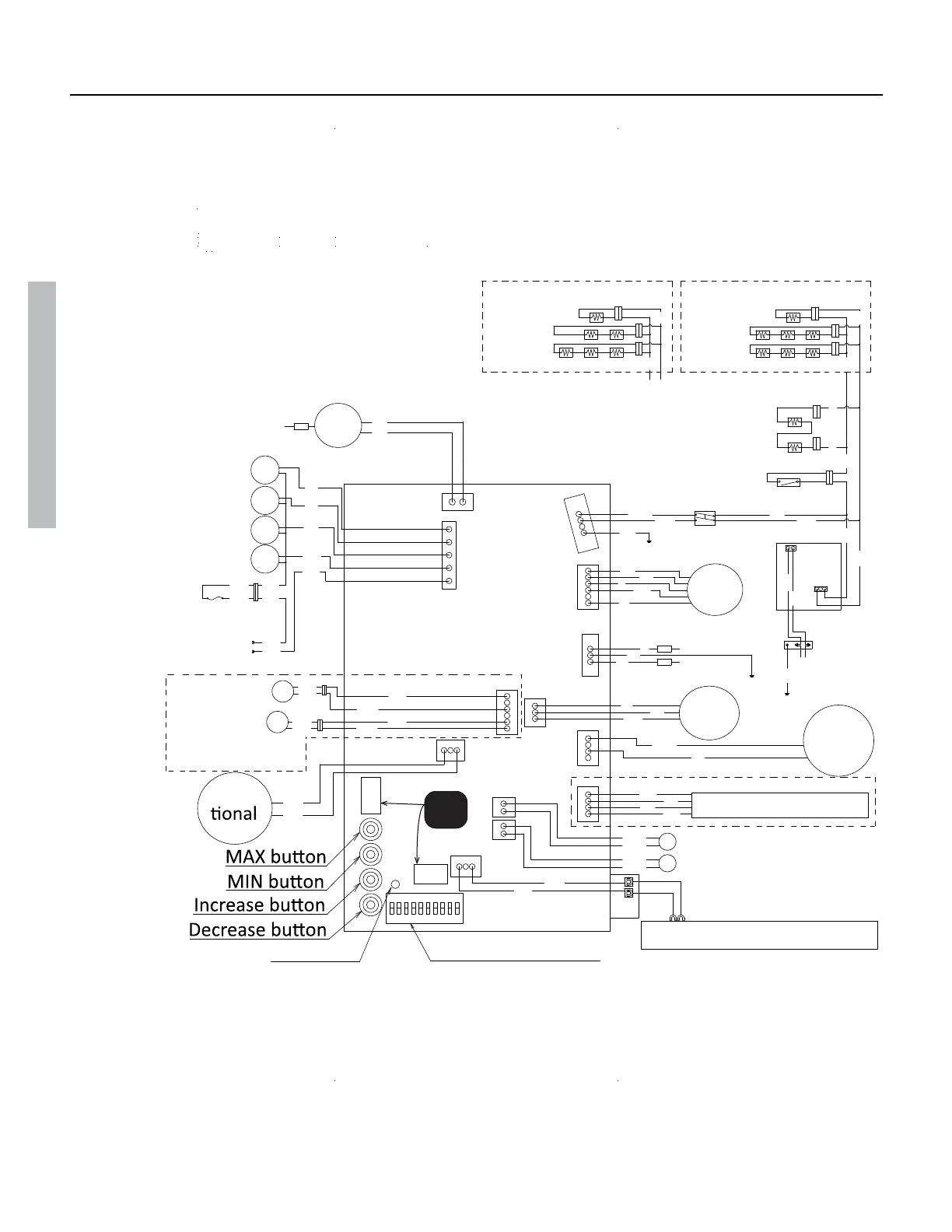
WIRING DIAGRAMS
Continued on the next page.
Figure 15
W: WHITE
R: RED
BK: BLACK
P: PURPLE
LB: LIGHT BLUE
BL: BLUE
G: GREEN
Y: YELLOW
O: ORANGE
BR: BROWN
9
8
7
65
4
3
21
10
OFF
Temperature remote controller
R
BK
R
W
BK
Ground
G
O
W
Y
BL
O
R
PCB
W
120 VAC
G
Ground
SW
Ground
W
BK
G
Igniter rod
P
73
53
9
3
O
R
G
LB
BL
O.H.C.F.
BL
Hi-
limit
Switch
BL
Gas
Propor-
Valve
W
R
BL
BL
BL
BL
P
BK
BK
W
BK
BK
Outlet thermistor
Inlet thermistor
Surge
box
Hi-limit switch
for exhaust
Exhaust
thermistor
W
W
W
W
BK
W
BL
R
BK
Temperature controller
Heater
Heater
Heater
240/340 Outdoor
Heater
BK
Y
Y
Y
Y
Y
Y
W
W
W
Y
Flame rod
AFR rod
BK
W
Thermostat
Heater
Heater
Heater
240/340 Indoor
SV3
SV2
SV1
MV
IG
Flow
Adjust-
ment
Valve
Flow
Sensor
FM
240/340 Indoor Only
240/340 Indoor Only
Not
Used
For instructions on how to use checkpoints during troubleshooting, refer to the water heater’s maintenance
sheet. The maintenance sheet is stored in a pouch on the inside of the water heater’s front cover.
 Loading...


