MAINTENANCE
MAINTENANCE
54 • On-Demand Water Heater Service Handbook for 240, 340 & 540 Condensing Models
6.4
Inspect the gasket. Minor
surface tears are acceptable.
If the gasket shows major
separaons, replace the
gasket before the unit is
returned to service. (The
parts list starts on page
75; burner assembly
components are idened
on page 73.)
1. WARNING! Natural Gas and LP
models use different dampers.
Failure to install the correct damper
for your model can cause carbon
monoxide poisoning. Failure to
observe this warning could lead to
carbon monoxide poisoning.
Transfer the burner damper (item
112, p. 73) from the original
burner to the new burner.
-OR-
Install a new burner damper if one
is needed (item 112, p. 73).
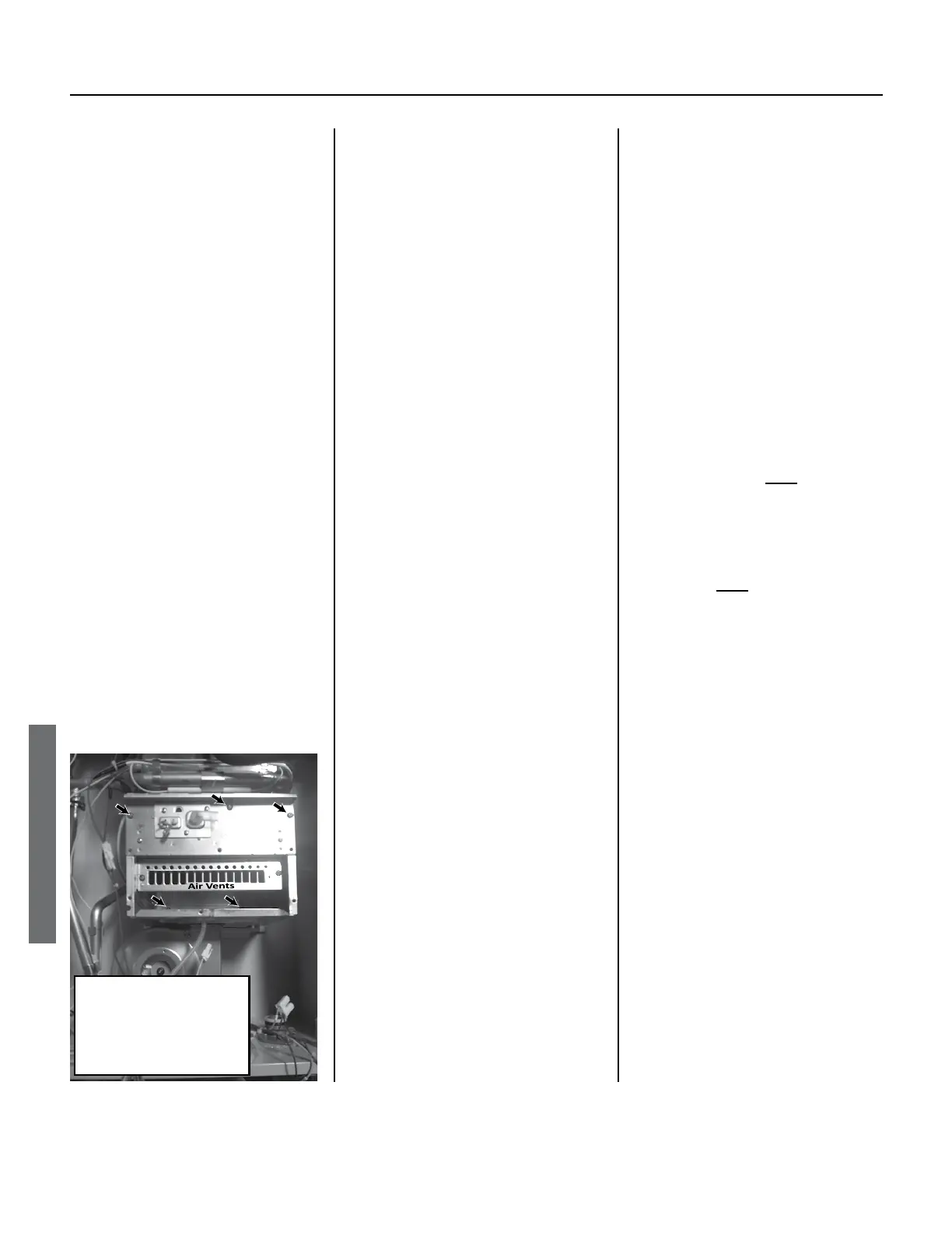
Burner Removal:
Remove one screw at
each arrow locaon.
(5 total.)
Figure 45.
2. Install the burner into the
There are grooves on the sides
between.
2.1 Insert and hand ghten two
screws below the burner, at
the back (Figure 45). These
screws will secure to the
back of the cabinet. You may
need to push the assembly
up some in order to line up
the holes.
2.2
Insert three screws along the
top poron of the burner, then
hand ghten them. See Figure
45.
3. Install the manifold plate/gas
valve assembly (item 102, p. 73)
follows:
3.1 If you removed the white
connectors from the
solenoids, reconnect them.
•
Match the printed
number on the wire
to the corresponding
number that is stamped
on the solenoid body.
See Figure 46.
•
For example, if “73“ is
printed on a wire, its pin
should plug into the side
of the connector that
has the number “73”
stamped closest to it.
3.2
Slide the gas valve/manifold
plate onto the gas inlet
connecon. (The gas inlet is
located at the boom, right-
hand corner of cabinet.)
You may need to rotate
the gas valve while sliding
it down for an easier t.
The tab on the gas valve
connecon should line up
behind the tab on the gas
inlet connecon.
3.3
Secure the gas valve to the
gas inlet by installing the
brass screw through both
tabs at the connecon
(hand-ght only). See Figure
or Figure 42 (p.
50).
3.4
Line up the manifold plate
with the holes on the burner
and combuson box.
3.5
Insert and hand ghten
the top center screw on
the manifold plate. Do not
overtighten.
3.6
Secure the manifold plate
by hand ghtening the
remaining screws around the
outside edge of the plate.
Do not overtighten.
If necessary, see Figure 43,
p. 53.
NOTICE: Be sure to reinstall
the igniter assembly at the
top, right-hand corner of the
manifold plate.
3.7
Aach the clear air tube
from the boom of the
combuson chamber to the
port on the le side of the
gas valve. (See Figure 47.)
4. Reconnect the plug and receptacle
that you disconnected earlier (i.e.,
the ones with the yellow wires).
This connector is shown just above
the “Main Gas Valve” in Figure 41
 Loading...


