MAINTENANCE
50 • On-Demand Water Heater Service Handbook for 240, 340 & 540 Condensing Models
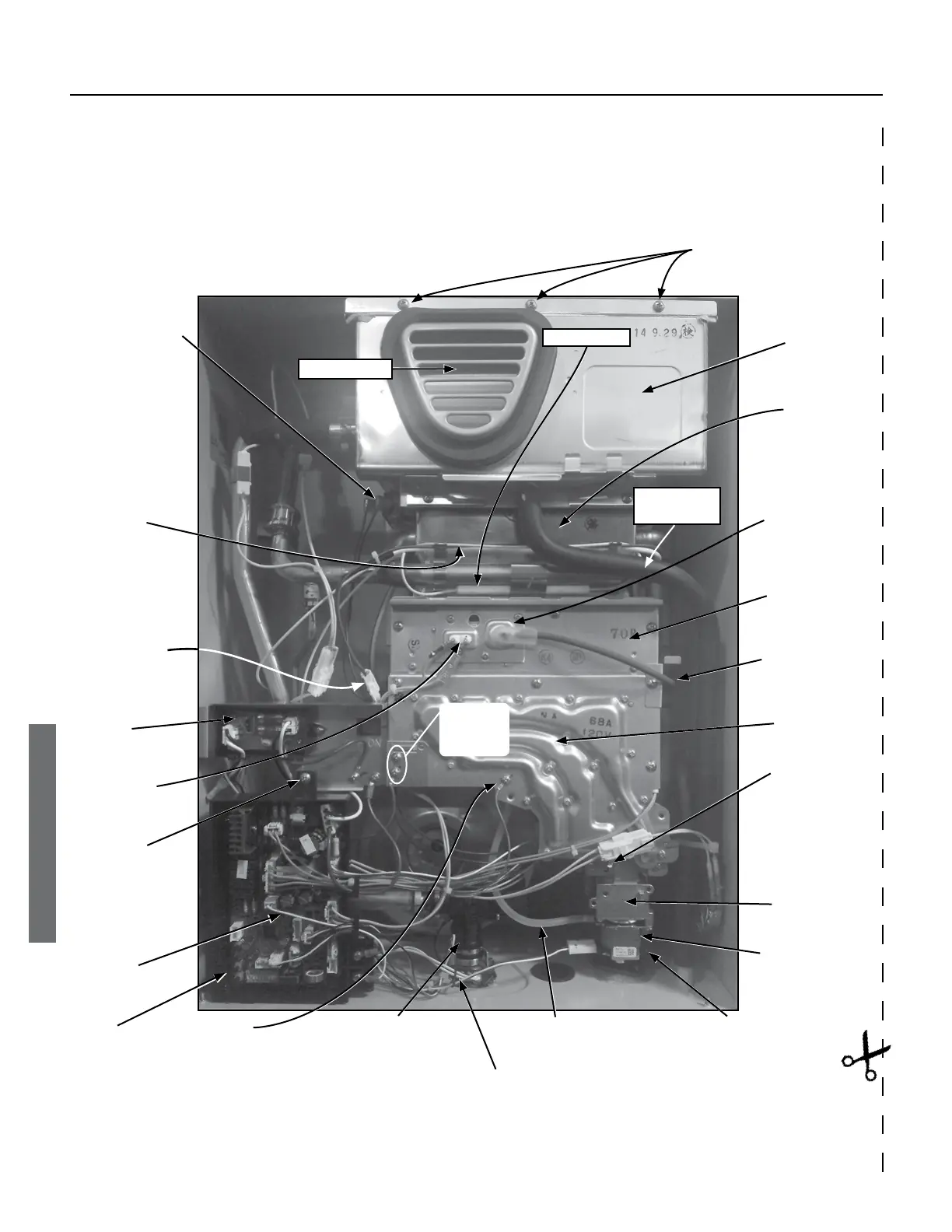
Outlet
Thermistor
(behind PCB)
NOTE: 540 outdoor models include a heat exchanger thermistor and a
bypass valve which are not shown in this graphic. However, their locations
Pipe Heater
Condensate
Drain Tube
Three Screws
Secure the Secondary Heat
Exchanger to the Case
High Limit Switch
(Heat Exchanger)
Primary Heat
Exchanger
Igniter Rod Wire
Connection
Secondary Heat
Exchanger
Over-heat
Cutoff Fuse
(OHCF)
Flame Rod
Connections
This Screw
Secures the
Computer
Board
Assembly.
Fuse Box
Computer
Board (PCB)
Exhaust Vent
See also “Component Diagrams/Item Numbers” which starts on page 71.
Connector for
Overheat Cutoff
Fuse (Blue Wires)
Manifold Plate
Igniter Assembly
(not visible)
Brass Manifold
Test Port Screw
Gas Proportional
Valve (GPV)
Main Gas Valve
Brass Screw Securing
Gas Valve to Gas
Inlet Connection.
Flow Sensor/Control
Valve (Behind Wires)
Ground
Connection
Clear Plastic Tube
(Combustion Chamber Tube)
Figure 42 .
Burner
Screws (2)
Securing
Fuse Box
Inlet Thermistor (black wires)
 Loading...


