TROUBLESHOOTING
TROUBLESHOOTING
On-Demand Water Heater Service Handbook for 240, 340 & 540 Condensing Models • 21
•
Multi-Link System:
Push the Alarm Reset button on
the multi-unit controller to clear
the code.
(Indoor models only.) This
code indicates that the exhaust
temperature exceeded limits and that
the heater was not able to reduce
the exhaust temperature, forcing the
exhaust high limit switch to trip and
shutdown the burners.
1. Check for excessive vent length and
for any blockage in the intake air
and/or exhaust.
2. Check for dust or lint in the
burner and heat exchanger in
contaminated installation areas.
3. Check the incoming water
temperature. If it is above 140°F,
the exhaust temperature may be
too high. Reduce the supply water
temperature.
4. Check the resistance of the thermistor.
Refer to “Code 311, 321, 331 or 341:
Thermistor Failure,” page 16.
5. Check the manifold pressure.
See “Checking and Adjusting the
Manifold Gas Pressure,” page 34.
This code indicates imperfect
combustion. This can be caused
by insufficient intake air or exhaust
obstructions.
See also “Error Code: 101.”
WARNING! Familiarize yourself with the
components before attempting these
procedures. Use the Installation Manual
and reference the component schematic
on the last few pages of the manual.
Safety first! These procedures must be
performed by licensed, qualified service
professionals only. Failure to observe
this warning could lead to personal
injury or death.
A.O. Smith is not liable for the actions of
the technician if he/she fails to adhere to
any or all safety procedures, specifically in
regards to electrical and gas safety.
1. Check the rating plate to verify that
the gas type of the water heater
matches the gas type applied to
the unit. Next, make sure that
the gas-type DIP switch setting is
correct. (See page 23.)
2. Verify that the venting meets the
requirements specified in the
installation manual (e.g., vent
diameter and length).
3. Verify the DIP switch
settings.
3.1 Are the DIP
switches set for
the correct vent
size and length?
Refer to Dip
Switch Sengs,
p. 23 for the
correct sengs.
Each 90-degree
elbow is equal to
5 feet of straight
pipe. Refer to
the installaon
manual for vent
requirements.
3.2
Is the heater set
to the correct
elevaon? The
default seng
for your water
heater is 2,000
. above sea level. A DIP
switch change is required for
installaons that are higher
than 2,000 feet above sea
level. Refer to “Dip Switch
Sengs” on page 23. One
of its tables lists the correct
DIP switch sengs for each
elevaon range.
4. Check the following:
Is the gas supply pressure within
specied limits when the heater is
in standby and when it is running?
If the pressure dierence between
standby and maximum ring is greater
than 1 inch W.C., the supply line,
gas meter, and/or regulator may be
undersized. NOTE: In Canada, do
not exceed the maximum allowable
pressure drop permied by B149.1.
Verify that the gas lines are sized
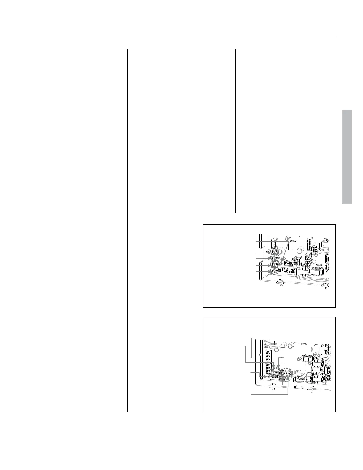
240 (T-H3J) / 340 (T-H3S) model
MAX buon
MIN buon
Increase buon
Decrease buon
540 (T-H3) model
MIN buon
MAX buon
Increase buon
Decrease buon
Manifold port
Computer board
To manometer
Tube
Green LED
240 (T-H3J) / 340 (T-H3S) model
MAX buon
MIN buon
Increase buon
Decrease buon
540 (T-H3) model
MIN buon
MAX buon
Increase buon
Decrease buon
Manifold port
Computer board
To manometer
Tube
Green LED
Green LED
Figure 7.
Figure 8.
 Loading...


