MAINTENANCE
MAINTENANCE
On-Demand Water Heater Service Handbook for 240, 340 & 540 Condensing Models • 57
5.4
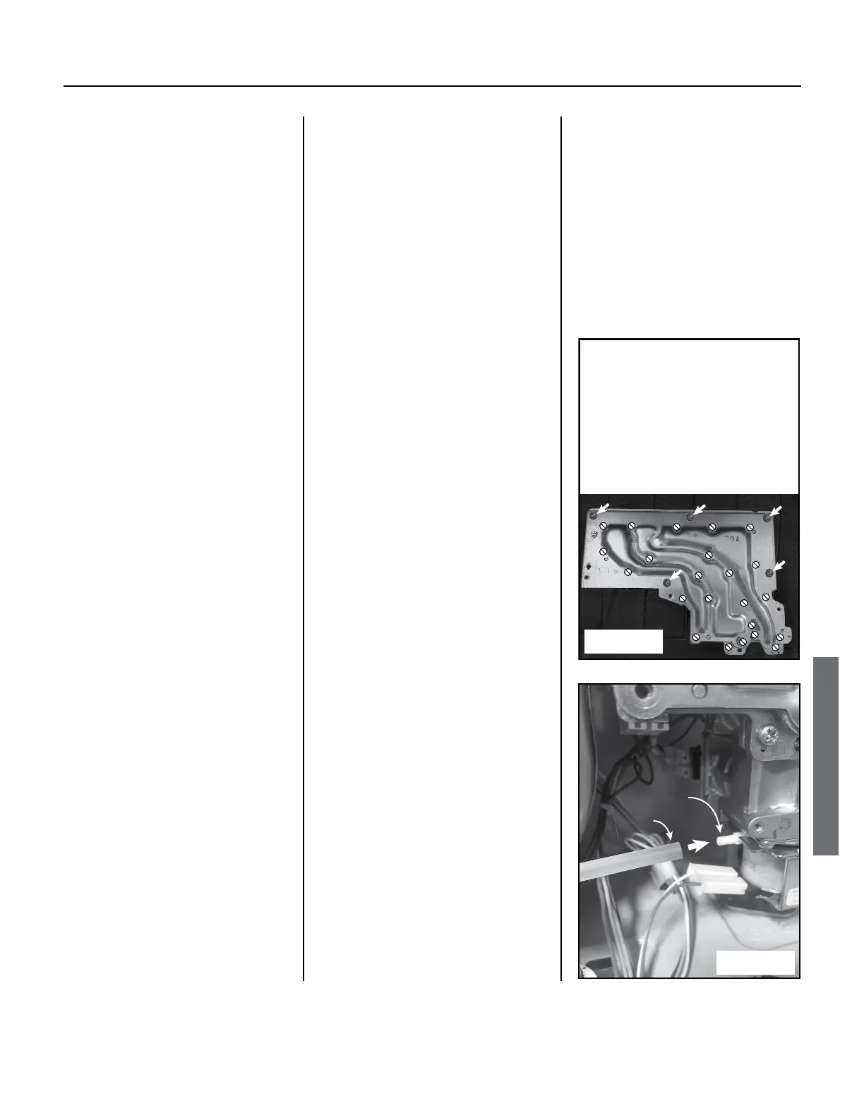
Disconnect the clear air tube
o the le side of the gas
valve. (Figure 49.)
5.5
Remove the screw securing
the gas valve to the gas inlet
connecon.
•
The screw is located at
the bottom, right-hand
side of the gas valve. See
OR
Figure 42 (p. 50).
•
If necessary, disconnect
the condensate tube
from the bottom, right-
hand side of the cabinet
first.
5.6
Li the manifold plate/
gas valve assembly upward
to remove it from the gas
inlet connecon. (The gas
valve and manifold are sll
connected together.)
You may need to twist the
gas valve/manifold assembly
slightly.
5.7
Unplug the wire connectors
from the solenoid valves,
main gas valve, and
proporonal gas valve.
(These valves are connected
to the back corner of the
manifold plate.) There are
ve connectors that can
be unplugged from the
manifold plate assembly.
5.8
Inspect the gaskets on
the manifold plate for any
tears. If compromised,
replace with part number
100074229 (item 113) and/
or 100074230 (item 114).
See p. 73.
5.9
Inspect the o-ring (item 151,
p. 73) and gas inlet ring
(item 119, p. 73) at the gas
connecon for cuts or breaks.
If damaged, replace with
part number 100074242
(item 151) and/or
100074526 (item 119).
6. Install the gas valve/manifold
assembly. (See item 102, p. 73)
6.1
Aach a wire connector to
each of the solenoid valves as
described:
•
There are a total of
ve connectors to be
reinstalled.
•
Each connector has a dark
blue wire, except for the
proportional valve. The
other wire colors will vary.
•
Each set of wires has a tag
with a number on it, and
each solenoid valve has a
number stamped next to
it. During installation, each
wire number must match
its solenoid valve number.
See Figure 50.
•
Install each connector to
the solenoid valve with
the matching number
except as noted below.
•
The proportional valve
does not have a number
and is located at the
bottom of the assembly.
It has red and white
wires.
6.2
Make sure that the screen
inside the gas valve inlet is
sll in place.
Manifold Screws:
• DO NOT remove the screws
indicated by the white,
crossed-out circles.
• Remove the screws
indicated by the white
arrows.
Figure 48.
Gas Valve
Port
Air Tube
Figure
6.3
Slide the gas valve/manifold
plate onto the gas inlet
connecon. (The gas inlet is
located at the boom, right-
hand corner of cabinet.)
You may need to rotate the
gas valve while sliding it
downward. The tab on the
gas valve connecon should
line up behind the tab on the
gas inlet connecon.
 Loading...


