MAINTENANCE
MAINTENANCE
58 • On-Demand Water Heater Service Handbook for 240, 340 & 540 Condensing Models
6.4
Secure the gas valve to the
inlet by installing the brass
screw through both tabs at
the connecon (hand-ght
only).
See Figure 41 (p. 49) or
Figure 42 (p. 50).
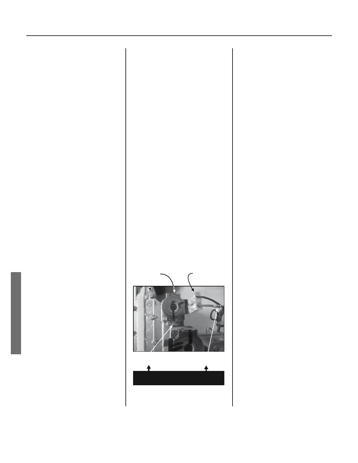
6.5
Aach the air tube from the
boom of the combuson
chamber to the port on the
le side of the gas valve.
(See Figure 49, page 57.)
7. Reconnect the plug and receptacle
that you disconnected earlier (i.e.,
the ones with the yellow wires).
This connector is shown just above
the “Main Gas Valve” in Figure 41
8. Install the fuse box assembly to
42 (p. 50).)
it to the manifold plate.
Install the computer board (PCB):
9.1 Posion the PCB in place:
Small feet at the
boom must t into the
corresponding holes in the
case.
9.2
Insert and hand ghten the
screw at the top of the PCB
to secure it to the fuse box.
10. Verify that all manifold screws
have been reinstalled and hand
11. Complete the wiring:
Refer to Figure 41 (p. 49) or
Figure 42 (p. 50) as you complete
these steps.
•
Install the green ground wire
onto the manifold plate.
(See “Ground Connection” in the
figure noted above.)
•
Insert the connector from the
power supply cable to its port on
the fuse box. (See “Fuse Box” in
the figure noted above.)
•
Reinstall the flame rod/AFR
wires.
(See “Flame Rod & AFR Wire
Connections” in the figure noted
above.)
12. INDOOR MODELS: Connect the
wires from the temperature
controller (item 722, page 71) to
the computer board.
The correct receptacle for your
model is shown in one of these
•
240 (T-H3J) and 340 (T-H3s)
Models. Page 30.
(locations vary)
Numbered
Wire
Stamped
Number
In each case, these numbers
must match.
Connectors have no polarity.
Figure 50.
See “Temperature Controller”
•
540 (T-H3) Models. Page 31.
See “Temperature Controller.”
13. Verify that all gas and water
Be sure that you reconnected the
right-hand corner of the cabinet.
14. Slowly open the gas valve and
check for leaks. If any gas leaks
WARNING! Failure to prevent gas
leaks can result in an explosion,
severe injury, or death.
15. Turn on water to the heater and
16. Verify that there are no water or
gas leaks.
17. Outdoor models:
Reinstall the front cover.
INDOOR MODELS:
Insert the temperature controller
into the opening of the front cover,
then reinstall the front cover.
If there are any questions, please
contact technical support.
 Loading...


