TROUBLESHOOTING
TROUBLESHOOTING
On-Demand Water Heater Service Handbook for 240, 340 & 540 Condensing Models • 31
W: WHITE
R: RED
BK: BLACK
P: PURPLE
LB: LIGHT BLUE
BL: BLUE
G: GREEN
Y: YELLOW
O: ORANGE
BR: BROWN
87
65
4
3
2
1
ON
654
3
2
1
ON
R
W
G
Y
PCB
W
120 VAC
G
Ground
SW
Ground
BK
W
G
BK
W
Surge
box
73
53
9
3
BL
BL
R
BK
R
W
BK
BK
BK
BK
BK
BK
W
BK
W
BK
Hi-limit switch
for exhaust
Exhaust
thermistor
W
W
W
W
Heater
Y
Y
Thermostat
BK
O
Ground
Flame rod
AFR rod
BK
W
W
BL
R
BK
Temperature controller
BK
BK
W
Green LED
Bank of
Bypass
Valve
R
W
BR
Y
BL
Gas
Propor-
Valve
R
Y
O
BL
W
FM
IG
Igniter rod
P
P
exchanger Heat
thermistor
Inlet thermistor
Outlet thermistor
Temperature remote controller
(oponal accessory)
Parent
1
2
Flow
Sensor
Flow
Adjust-
ment
Valve
Heater
Heater
540 Outdoor
Heater
Y
Y
Heater
Y
Y
Heater
Heater
540 Indoor
Hi-
switch
limit
O.H.C.F
MV
SV1
SV2
SV3
BL
BL
BL
BL
LB
G
O
R
BL
540 Indoor Only
540 Indoor Only
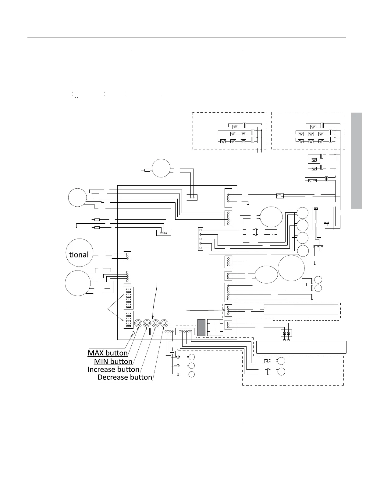
DIPswitches
Note: The two
receptacles below
the buttons are
not used.
This receptacle
is used for 540
indoor models
only.
For instructions on how to use checkpoints during troubleshooting, refer to the water heater’s maintenance
sheet. The maintenance sheet is stored in a pouch on the inside of the water heater’s front cover.
Figure 16
 Loading...


