SERVICE PROCEDURES
SERVICE PROCEDURES
36 • On-Demand Water Heater Service Handbook for 240, 340 & 540 Condensing Models
49 or Figure 42, p. 50.
3. Find the white clip at the end of
the two blue braided wires coming
from the OHCF. (Refer to Figure 23
on page 35.)
4. Unplug the connection.
5. Test resistance at the end of the
OHCF with a digital volt/ohm meter
(Figure 23). Resistance should
measure 1 ohm or less. Reconnect
the plug.
If the resistance exceeds 1 ohm,
replace the OHCF (part 319143-
149). Replacing this part will
require you to remove the heat
exchanger. Follow the “Replacing
the Heat Exchanger” instructions
which are found in the “Service
Procedures” section. Inspect the
heat exchanger for any burn marks,
hot spots, cracks, etc.
6. Restore power and test the unit.
Checking the Flow
Sensor
If the water heater is connected to
the water, gas, and power supplies
correctly, but the fan motor does
not initiate when water flows, then
the flow sensor may not be able to
detect water flow. Water flow must
be detected for the water heater to
initiate operation.
Tools and Materials:
Flashlight
Towels
The flow sensor (item 402, p. 74) is
located below the water control valve
at the cold inlet. (See also Figure 41,
p. 49 or Figure 42, p. 50.) Its flow
rate is determined by an impeller that
spins as water runs through it.
To check the flow sensor,
1. If you have a remote, you can
check for flow rate by turning on
power to the water heater. Push
the “Info” button three times. This
will display flow if the flow sensor
is working properly.
2. Remove the flow sensor as
described in “Flow Sensor/Control
Valve Removal and Installation,”
page 51.
3. Blow into the inlet of the flow
sensor. Watch to see if the
impeller spins. It should spin freely
for a few seconds. If it comes to
rest abruptly or doesn’t spin at all,
it should be inspected for blockage.
NOTICE: Do not try to disassemble
the flow sensor. If there is debris
that cannot be removed, or if the
impeller does not move freely,
replace the flow sensor/flow
control valve.
4. If you have an outdoor model
without a remote, test the flow
sensor as follows:
4.1 Reaach the ow sensor wires.
4.2
Turn power to the unit back on.
(GAS MUST STILL BE OFF.)
4.3
Blow into the ow sensor. If
the fan iniates, the ow
sensor successfully read the
airow and should now work
properly.
5. Reinstall the flow sensor as
described in “Installation” on page
51.
Cleaning the Rod
Assembly (Flame
Sensor and Air/
Tools:
Sheet of 100 Grit Sandpaper or
other suitable abrasive
#2 Philips Screw Driver
Replacement gasket,
part 100074219.
1. Disconnect power to the water
heater by unplugging it from the
wall outlet or turning it off at the
circuit breaker, as appropriate.
Verify that power is off using a volt
meter or similar device.
2. Remove the front cover. It is held
on by two screws on the top and
two screws on the bottom.
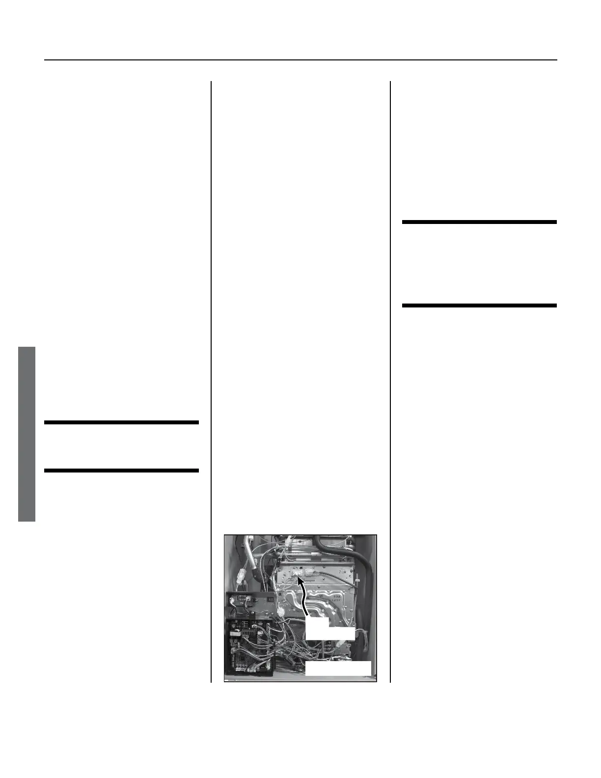
3. Remove the rod assembly as
described below. (See Figure 24.)
3.1 Locate the yellow and
orange wires located in the
center of the unit (beside
the sight glass).
3.2
Disconnect these wires.
NOTICE: The yellow wire
is locked onto the rod’s
Rod
Assembly
Figure 24.
 Loading...


