SERVICE PROCEDURES
SERVICE PROCEDURES
On-Demand Water Heater Service Handbook for 240, 340 & 540 Condensing Models • 37
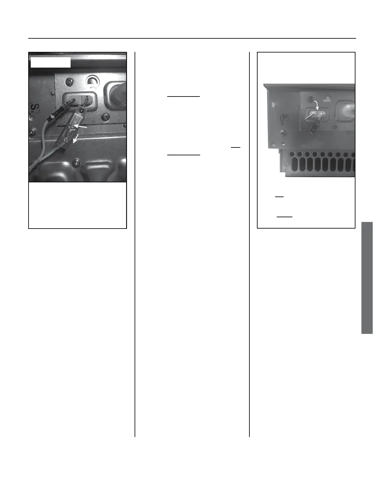
conducve spade. To release
the AFR rod connector,
follow the instrucons in
Figure 25.
3.3
Remove the three Phillips-
head screws holding the
panel in place.
3.4
Pull the assembly out.
NOTICE:
•
All pieces are separate.
•
Be careful to not drop or
lose the sight glass.
4. Inspect the ceramic insulator for
chips or cracks. (This ceramic
insulator holds the flame sensor
and air/fuel ratio rods in place.)
Replace it if any chips or cracks are
visible or if either rod moves freely
inside the ceramic.
5. Clean the flame sensor and air/fuel
ratio rod as described below. (See
Figure 26.)
5.1 Clean the poron of the
flame sensor that extends to
the inside of the burner. Use
100 grit sandpaper or other
suitable abrasive. Be sure
to remove any oxidaon or
contaminates.
5.2
Clean the poron of the air/
fuel ratio rod that extends to
the inside of the burner. Use
100 grit sandpaper or other
suitable abrasive. Be sure
to remove any oxidaon or
contaminates.
6. Reassemble the unit in reverse
order: gasket, rods, and metal
cover. Be sure to connect all 3
wires on the front of the burner.
Also, inspect all gaskets to make
sure that they are free of debris
and are not ripped or torn. If the
gaskets are ripped or torn, replace
them BEFORE reassembly.
7. Verify proper operation.
To remove the AFR rod
connector, pinch at the
locaon shown by the arrow,
then slide the connector off
the spade.
Pinch
Slide
connector
off spade
Figure 25.
Flame Rod /AFR
Assembly
Front of burner:
• Do not clean the extensions on
the outside (shown above).
• Clean the metal extensions on
the inside of the burner.
Figure 26.
 Loading...


