TROUBLESHOOTING
TROUBLESHOOTING
On-Demand Water Heater Service Handbook for 240, 340 & 540 Condensing Models • 23
TROUBLESHOOTING
TROUBLESHOOTING
DIP SWITCH SETTINGS
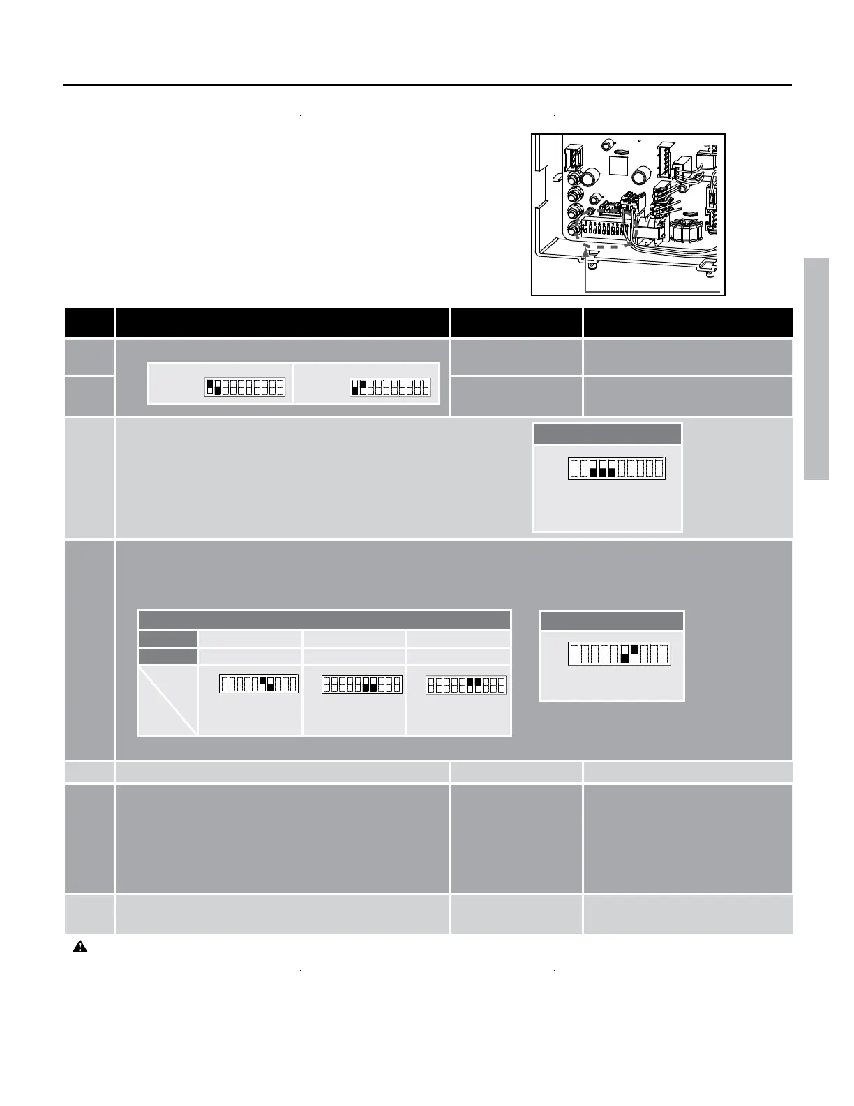
The computer board layout for all 240 and 340 models is identical. See “Wiring
Diagrams,” page 30. The DIP switches have certain special functions as shown
on the following table and generally should not need adjustment.
Verify the functions of each DIP switch carefully before changing any settings.
If you have questions, contact the technical service department.
Table 5: 240 (T-H3J) / 340 (T-H3S) models
NOTE: Dark squares represents DIP switches
Figure
: 240 (T-H3J) and 340 (T-H3S)
NO. FUNCTIONS ON POSITION
1 Gas type Propane Disable
2 Natural gas Disable
3
4
5
FM+, FM- and Input-
(Fan motor speed is increased automacally.)
6
7
Installaon sengs
8 N/A (Do not change switch posion.) N/A N/A (Default)
9 Output temperature sengs
(Default 120°F / 49°C)
140 °F (60
°C) 120 °F (49 °C)
(Default)
10* Deacvaon of the exhaust temperature control Enable Disable
(Default)
DEFAULT
No.3: OFF
No. 4: OFF
No.5: OFF
ON
Propane
ON
Natural
Gas
ON
Outdoor models
No. 6 : OFF
No. 7 : ON
OFF
ON
Set DIP switches shown
in the table below.
OFF POSITION
WARNING: Do not adjust DIP switch No. 10 without guidance from the technical service department. The only me
DIP switch 10 should be set to ON is when your unit is being hooked up to CAT III/IV metal vent with a maximum temp.
rang of 480° F. The No. 10 DIP switch deacvates the exhaust temperature control when set to the ON posion.
Failure to follow this warning can lead to personal injury, carbon monoxide poisoning, or death.
Vent sengs (Indoor models only)
3" venngs
5 to 20 (DEFAULT) 21 to 40 41 to 70
4" venngs
5 to 50 (DEFAULT) 51 to 100 N/A
No. 6 : ON
No. 7 : OFF
No. 6 : OFF
No. 7 : OFF
No. 6 : ON
No. 7 : ON
Set DIP switches shown in the table below depending on the vent length.
ON
ON
ON
For correct settings, see pages 26 and 27.
 Loading...


