SERVICE PROCEDURES
SERVICE PROCEDURES
On-Demand Water Heater Service Handbook for 240, 340 & 540 Condensing Models • 43
SERVICE PROCEDURES
SERVICE PROCEDURES
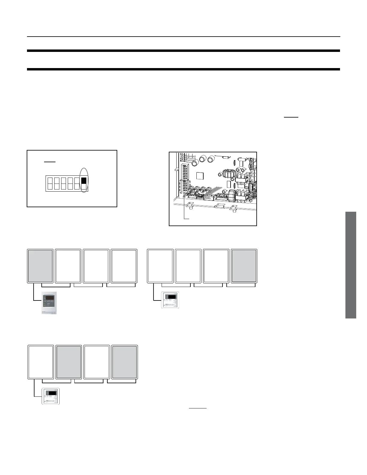
The 540 (T-H3) model can be connected to 520 (T-H2) or 710 (T-M32) models using the Easy-Link system. However, you must
change one DIP switch setting first. On each 540 (T-H3) computer board, change DIP switch no. 6 on the lower bank of
switches to the “ON” position. See Figure 35 and Figure 36.
Examples of correct Easy-Link connecons
Temperature remote controller :
9008172005 (TM-RE40)
540
(T-H3)
Previous
model*
Previous
model*
Previous
model*
1
Temperature remote controller :
9007603005 (TM-RE30)
Previous
model*
Previous
model*
540
(T-H3)
Previous
model*
Case 2
Temperature remote controller :
Previous
model*
540
(T-H3)
540
(T-H3)
Previous
model*
Case 3
* In each case, ”Previous model”
indicates a 520 (T-H2) unit or a
710 (T-M32) unit.
520 (T-H2) units and 710 (T-M32)
units cannot be linked in the
same system.
Figure 37.
ON
1
2
3
4
5
6
2
3
4
5
The dark square is the position to
which the DIP switch must be set.
DIP switch seng on the 540 (T-H3)
(Lower bank of DIP switches)
Figure 35
.
Lower bank of
: 540 (T-H3)
Figure 36
 Loading...


