MAINTENANCE
70 • On-Demand Water Heater Service Handbook for 240, 340 & 540 Condensing Models
•
Plug both spade
connectors (blue wires)
onto the heat exchanger’s
high limit switch. See
“High Limit Switch (Heat
Exchanger)” in Figure 41
(p. 49) or Figure 42 (p.
50).
•
Reconnect the flame
rod and AFR wiring. See
“Flame Rod & AFR Wire
Connections” on page
49 or 50.
•
Install both power plugs
at the fuse box. See
“Fuse Box” on page
49 or 50.
•
INDOOR MODELS:
◦ Plug in the high
limit switch and
exhaust thermistor
connectors. See the
top of Figure 41,
page 49.
◦ Plug the wires from
the temperature
controller into the
computer board
(PCB). These wires
are black, red, blue,
white.
If needed, refer
to one of the
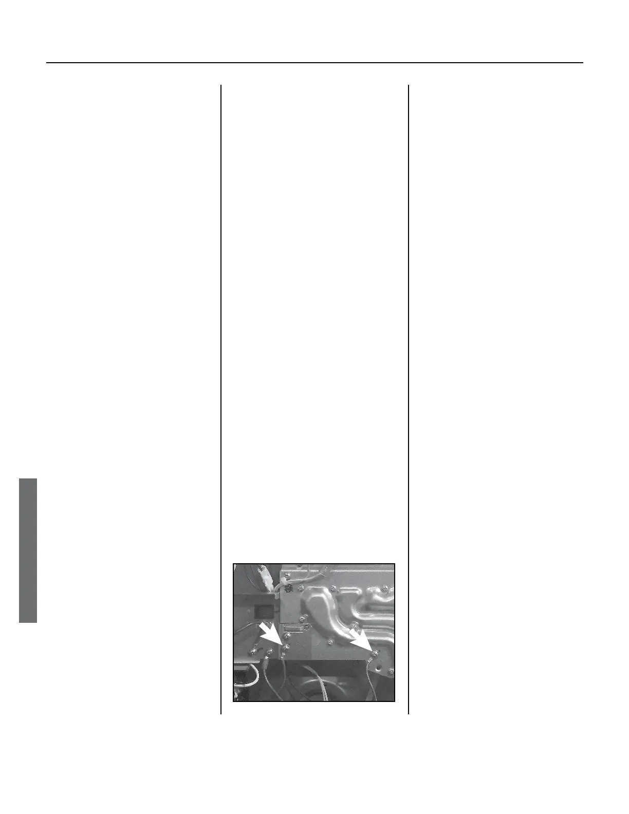
Fan
Manifold plate
Install ground wires at these two locaons.
Figure 72.
•
INDOOR MODELS:
Install the connector
with four white wires
into the computer board
as described below.
◦ If you have a 240 or 340
model, see “Hi-limit
switch for exhaust/
Exhaust thermistor” on
page 30.
◦ If you have a 540
model, see “Exhaust
thermistor/Hi-limit
switch for exhaust”
on page 31.
•
540 MODELS:
Be sure to reconnect the
wiring harness to the bypass
valve, then plug it into the
PCB. Wire colors: Red,
Yellow, White, Blue, Brown.
22.
inside the cabinet:
•
Locate the two unsecured
ground wires (green).
Secure them with screws as
shown in Figure 72.
•
Locate the plug and
receptacle with blue
wires. Plug them
together at the left-hand
side of the cabinet. See
“Over-heat Cutoff Fuse
(OHCF)” in Figure 41 (p.
49) or Figure 42 (p.
50).
(This blue wire assembly
has male and female
plugs that you must
plug together. There are
also two separate wires
on this assembly that
have spade connectors
on each end. You will
connect the spade
connectors during the
next step.)
schematics on page
30 or page 31.
•
540 MODELS ONLY:
Install the heat
exchanger thermistor
as shown on page 74.
See items 411, 454, and
NOTICE: Be sure that
the thermistor is fully
inserted into the opening
and that it is secured by
the 4-11 clip.
1.
2. Restore power to the water heater.
3. Open the gas valve slowly and
check for leaks.
WARNING! If any gas leaks appear,
power to the water heater. Failure
personal injury or death.
4. Turn on water to the heater and
5.
gas leaks.
6. Insert the temperature controller
into the opening of the front cover,
then reinstall the front cover.
If you have any questions, please
contact technical support.
 Loading...


