MAINTENANCE
MAINTENANCE
66 • On-Demand Water Heater Service Handbook for 240, 340 & 540 Condensing Models
exhaust flue.
•
Exhaust thermistor, gasket, bracket,
and screw. (See items 471, 718,
470, and 053 on page 74.)
•
Exhaust high limit switch (item 472,
page 74): it can be removed and
installed by sliding it through the
bracket.
•
Freeze protection heater, which is
shaped as a long rectangle (item
415, page 74) and located on
the front, right-hand side of the
secondary.
2. Complete the steps in “Installing
the Heat Exchanger Assembly.”
Installing the Heat
1. Fit the secondary heat exchanger on
top of the primary heat exchanger.
WARNING! Make sure that the
secondary heat exchanger. Failure
poisoning.
NOTICE: The copper pipes bend
easily. Do not allow them to bend
during assembly.
2.
holes line up. See Figure 66.
3. Secure the primary and secondary
heat exchangers together with
eight screws (two on each of the
four sides).
4. Insert the heat exchanger
assembly into the case with its
hole in the top of the case. (The
on the inside of the case.)
INDOOR MODELS: Make sure that
74) is on the inside of the case.
5.
screws as shown in Figure 63, page
64. This will secure the heat
exchanger assembly to the heater case.
6. Reconnect the cold pipe as follows:
6.3.1
Install the cold pipe as shown
on page 74. (See item 466.)
NOTICE:
◦ 240/340 MODELS:
Reconnect the top
termination. The bottom
termination will be
connected during later
steps.
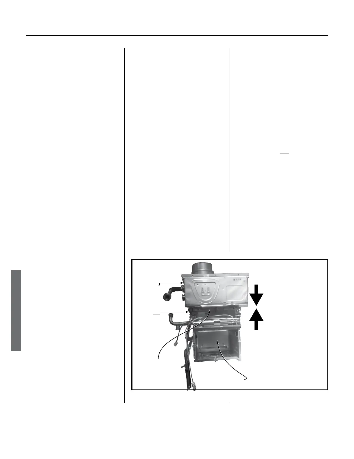
Secondary
Primary
1. Fit secondary on top
of primary. Make sure
flange on top of primary
fits into female opening
(Flange and female
opening not shown.)
2. Make sure all eight
sets of mounng holes
line up.
3. Secure primary to
secondary with eight
screws (two on each of
the four sides).
Eight mounng holes
around perimeter.
Combuson Chamber
Figure 66.
◦ 540 MODELS: Reconnect
the top and middle
terminations. The bottom
termination will be
connected during later
steps.
6.3.2
Secure the connecon(s) with
clip(s).
NOTICE: “16-25” is marked on
the end of the clip(s). All such
clips are marked on the end in
the same manner.
6.3.3
Reaach two ceramic heaters
to the cold pipe, one at the top
and one at the boom. See
items 466, 414, and 415 on
page 74.
7. Reconnect the heat exchanger out
pipe (item 467, page 74) as shown
•
The top connection should be
connected already. If it is not,
reconnect it as shown on page 74.
•
The out pipe must be connected at
each end with a 16-25 clip.
 Loading...


