MAINTENANCE
MAINTENANCE
On-Demand Water Heater Service Handbook for 240, 340 & 540 Condensing Models • 67
8. Reconnect the drain pipe (item
465) as shown in the diagram on
page 74.
Secure both ends with 6-15 clips.
chamber. (See Figure 66.) There
are grooves on the sides of the
spacers that will will slide along the
grooves.
burner are rigid, but the spacers
along the top of the burner are
fragile and can be damaged easily.
are in alignment with the grooves
before sliding the burner into
place.
9.3.1
Insert and hand ghten two
(2) screws below the burner,
at the back. (See Figure 61,
page 63.) These screws
will secure the burner to the
back of the cabinet. You may
need to push the assembly
up some in order to line up
the holes.
9.3.2
Insert and hand ghten
three (3) screws along the
top, front poron of the
burner (Figure 61, p. 63).
10. Insert the outlet tubing into the
sure that the brass ring on the
tube goes all the way in and is
Secure it with a 16-25 clip. See
item 462 on page 74.
11.
of the secondary heat exchanger. (See
Item 416 on page 74. )
12. Install the fan with the air inlet
facing toward the front as follows:
12.1 Slide the fan’s anges into
the slots on the boom of
the combuson chamber.
(The fan’s air inlet must face
outward.)
12.2
Line up the holes, then insert
and hand-ghten two (2) hex
head screws with washers
(item 54). See page 73.
NOTICE: There are two
holes on the boom of the
case through which you can
reach both screws with an
8-inch long phillips screw
driver (#2).
page 63.
13. Install the gas valve/manifold
assembly as described below.
(See also item 102, p. 73)
13.1
Aach a wire connector to
each of the solenoid valves
as described:
•
There are a total of five
connectors to be reinstalled.
•
Each connector has a dark
blue wire, except for the
proportional valve. The
other wire colors will vary.
•
Each set of wires has a tag
with a number on it, and
each solenoid valve has a
number stamped next to
it. During installation, each
wire number must match
its solenoid valve number.
See Figure 68.
•
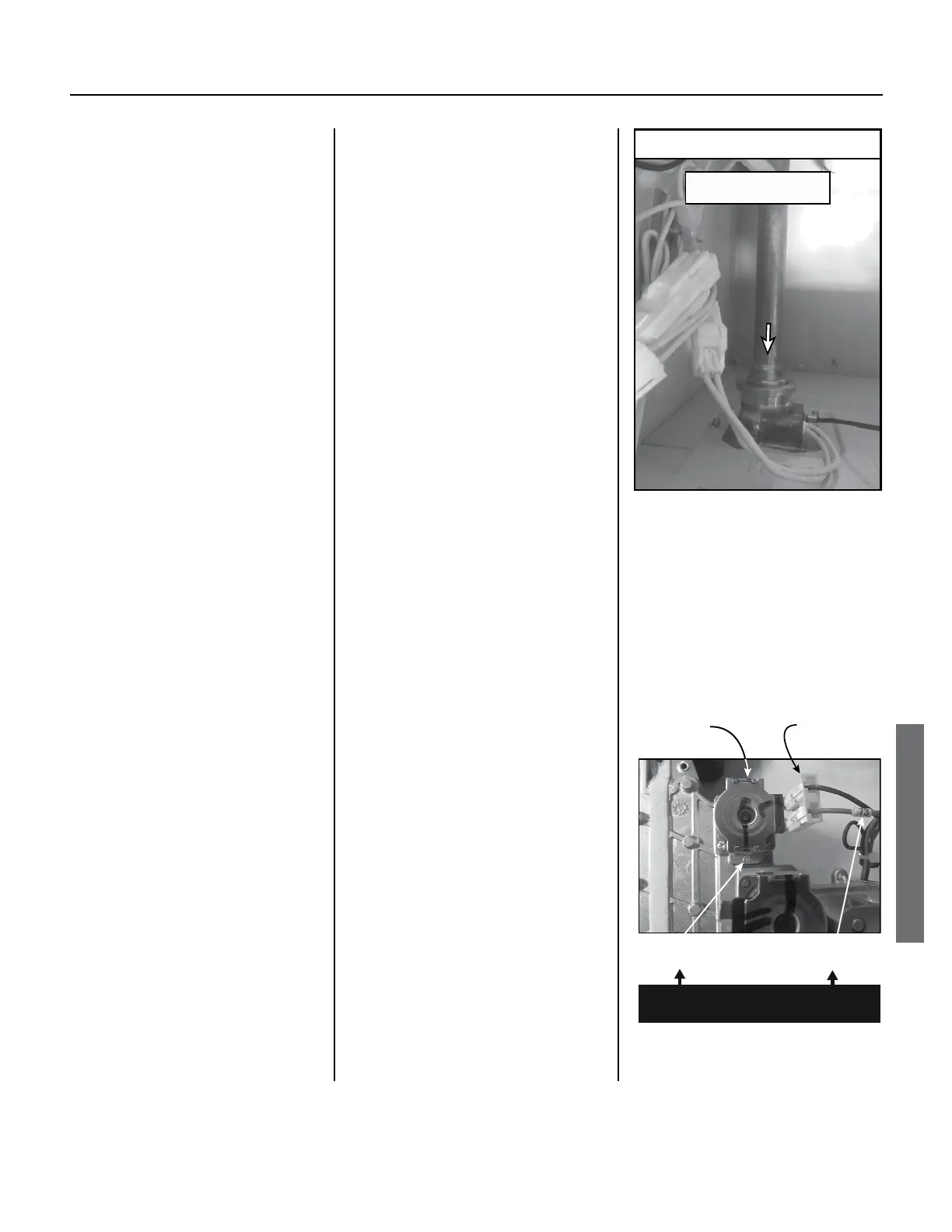
Install each connector to
Hot Outlet Tube Installation
Once tube is installed,
secure with fastener 16-25.
Bottom, left-hand side of case
Figure 67.
(locations vary)
Numbered
Wire
Stamped
Number
In each case, these numbers
must match.
Connectors have no polarity.
Figure 68.
 Loading...


